

Where do you begin when troubleshooting a fault in a PLC-controlled system? An issue with the PLC program is seldom the cause of the fault unless it has been altered by human intervention. Usually, the problem stems from the field devices or the PLC I/O modules.
In this article, we’ll explain the characteristics of sinking and sourcing PLC inputs so you can effectively troubleshoot and identify where the fault originates.
Let’s start with the terms Sinking and Sourcing, which can often be confusing.
Sinking and sourcing
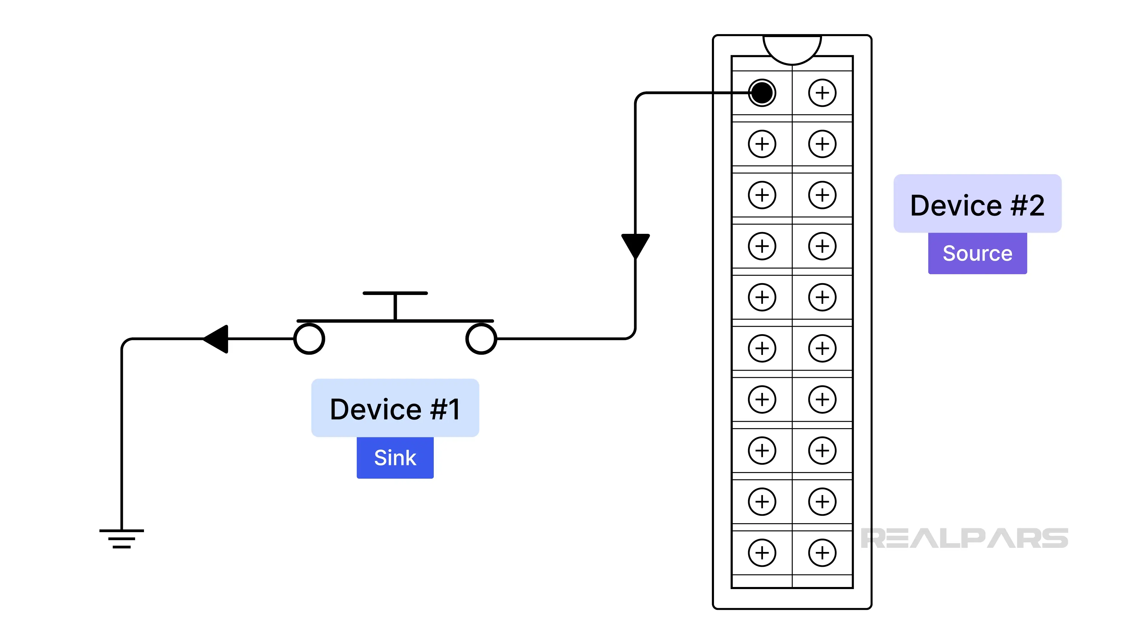
In simple terms, it’s all about defining the direction of conventional current flow between two devices.
If current is flowing from Device #1 to Device #2, Device #1 is Sourcing the current, and Device #2 is Sinking the current.
Alright, suppose Device #1 is an input field device, such as a switch, and Device #2 is a PLC digital input module. If current flows from the switch to the input module, then the switch is the source and the input module is the sink.
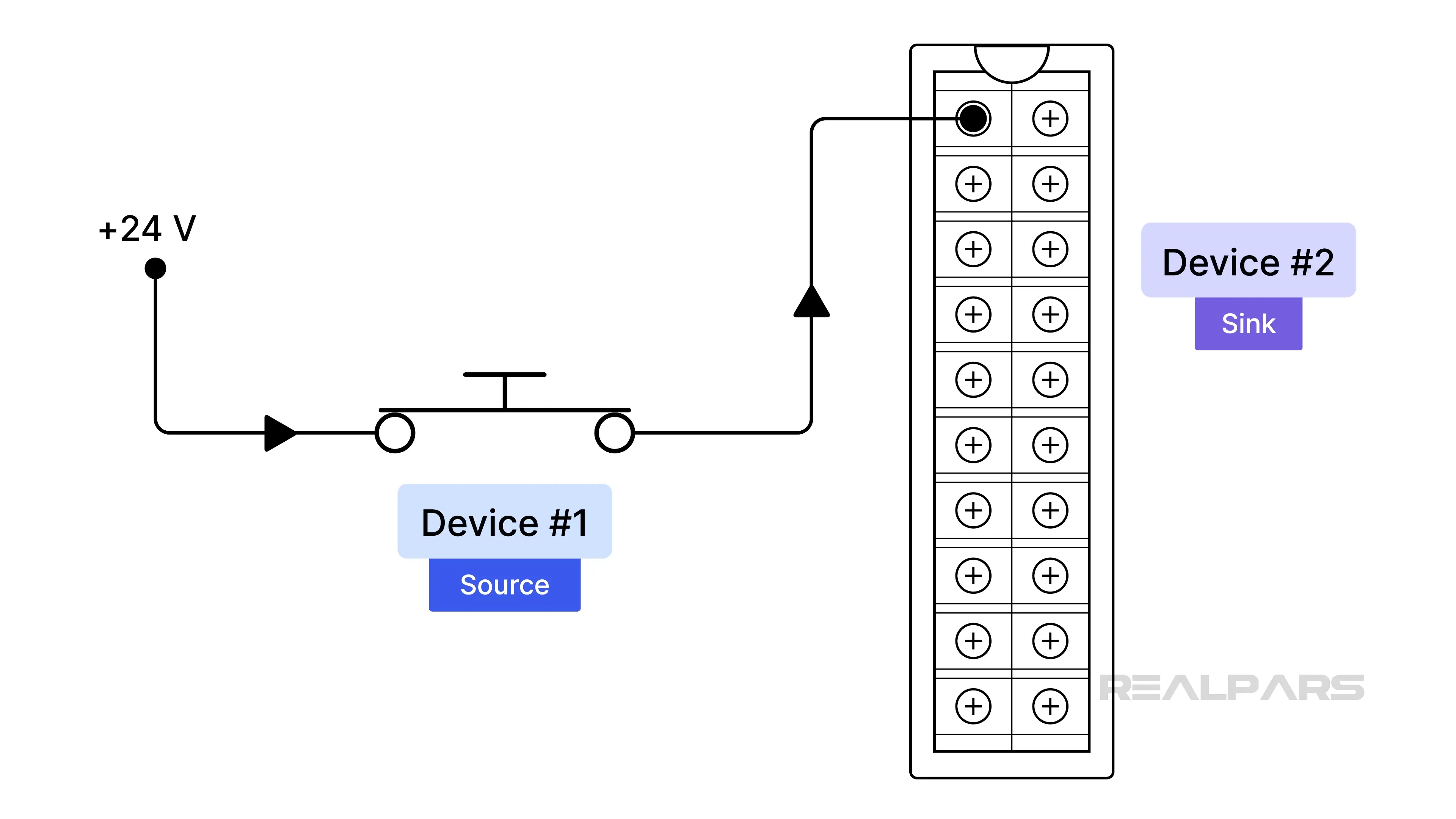
If current flows from the input module to the switch, then the input module is the source, and the switch is the sink.
PLC vendors offer both sinking and sourcing input modules.
For example, the Allen-Bradley 1756-IB16 is a 16-input, 24-volt sinking input module.
The Allen-Bradley 1756-IV16 is a 16-input, 24-volt sourcing input module.
Input field devices
Let’s move on to a discussion about 2-wire and 3-wire input field devices.
2-wire devices
The majority of 2-wire devices are passive, meaning they do not require power to operate and simply open or close a circuit. Examples include pushbuttons, limit switches, and other mechanical devices. We can consider 2-wire passive devices to be either sinking or sourcing.
There are also active 2-wire devices that require power to operate and may be polarity-dependent.
3-wire devices
3-wire devices are part of the active device family that require power to operate. Examples include proximity sensors and photoelectric switches.
The wire colors follow a standard. The brown wire connects to the positive supply, usually +24 volts DC. The blue wire connects to the power supply return. The black wire acts as the signal output and supplies input to another device, such as a PLC input module.
3-wire active devices are either sinking or sourcing.
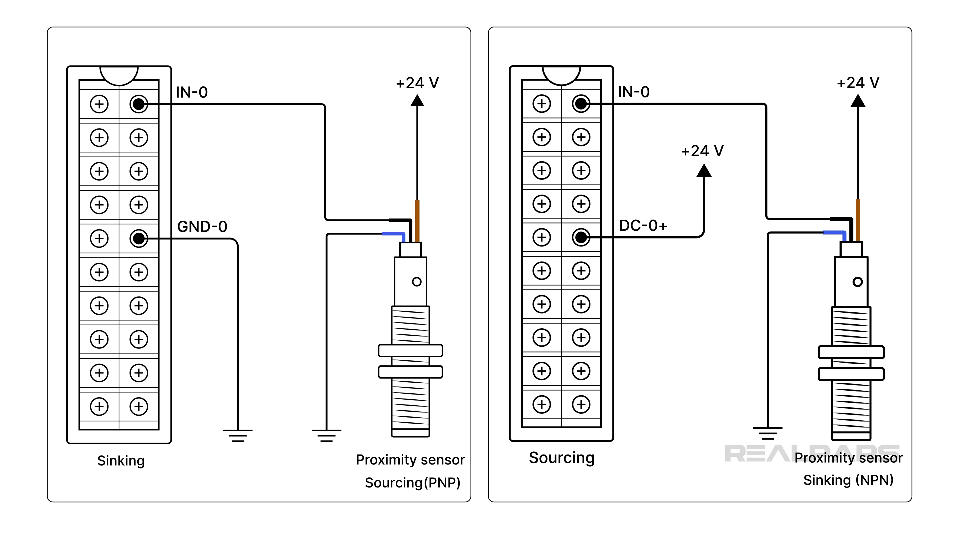
It's vital to verify that 3-wire devices are compatible with the intended input modules.
A 3-wire sourcing sensor, also called a PNP sensor, must connect to a sinking input module. A 3-wire sinking sensor, also called an NPN sensor, must connect to a sourcing input module.
Many PLC troubleshooters take advantage of the input module LED indicators. Having said that, it’s essential to understand what the LED indicators are telling you and how they can be misleading.
Using LEDs for troubleshooting
Let’s start with a sourcing sensor connected to Input 0 on a sinking input module. We’ll use the AB 1756-IB16 digital input module as an example.
Each input circuit has an associated ST LED that is intended to indicate the input status.
If the LED 0 is on, it suggests that the sourcing input device is supplying +24 volts to the module’s input 0 terminal. The module will interpret this voltage as a logic “1” and use it to operate within the PLC program.
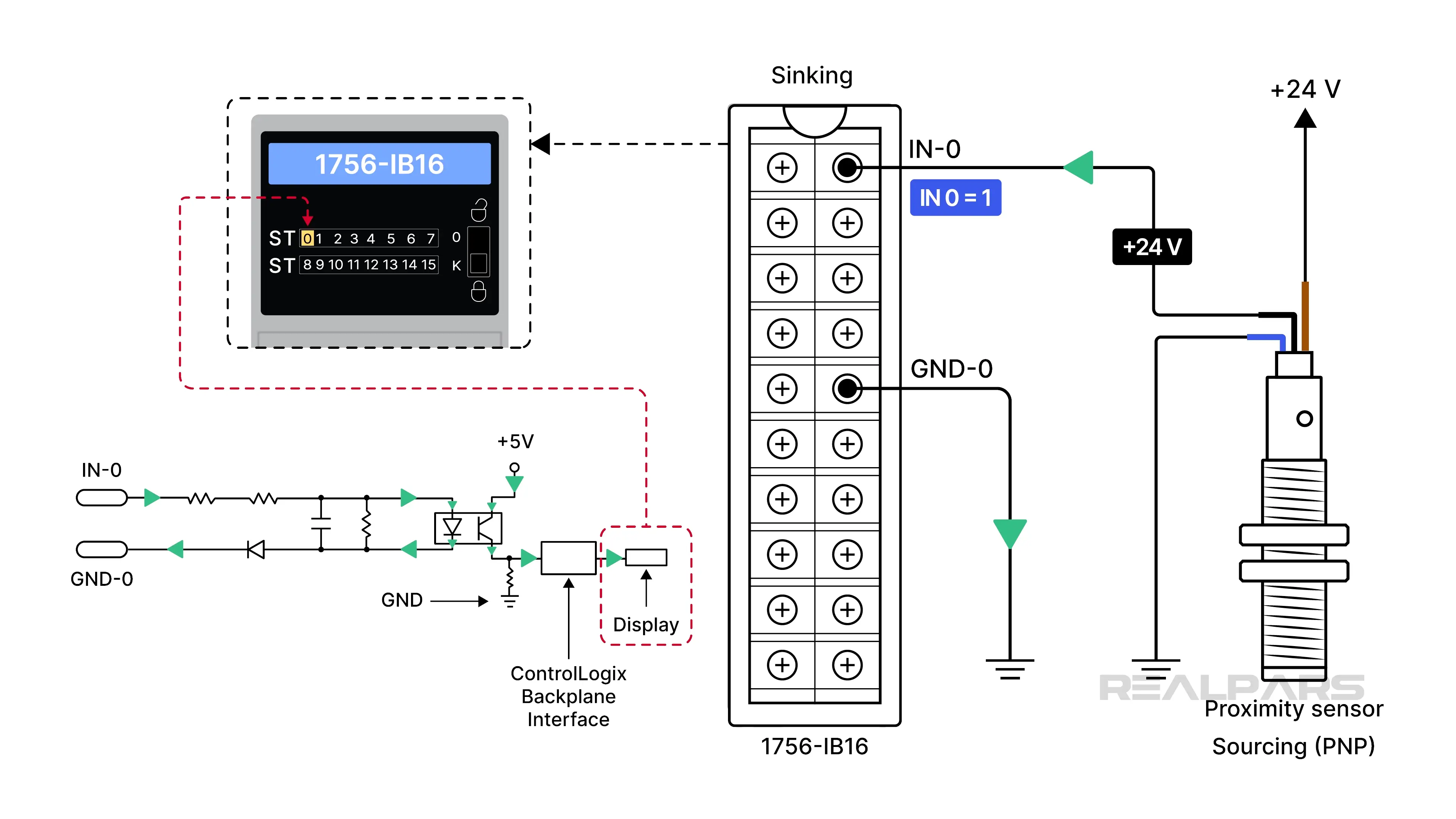
If LED 0 is off, it is often assumed that the sourcing input device is providing 0 volts to the module’s input terminal 0, which the PLC program will interpret as a logic “0”. However, we all understand what 'assume' means.
We said earlier that the LED indicators can be misleading. Why is that? Well, the LED may be on, but the voltage present may not be what you expect. The same can be said when the LED is OFF.
The only way to be sure is to measure the voltage at the input module terminal.
According to the 1756-IB16 input specifications, any input voltage above the 10-volt threshold will be detected as ON by the module. A 15-volt input will be interpreted as a logic “1” in the PLC program. However, this may indicate issues with the field device, wiring, or possible corrosion.
An input below 5 volts will be recognized as OFF by the module. How is it possible for the voltage at the module input to be close to 5 volts when the sourcing sensor is off?
A sourcing sensor turns off by opening an internal semiconductor switch, not by grounding it. The module input is floating, making it susceptible to voltages caused by normal sensor leakage current.
Sinking sensors with sourcing PLC inputs
Ok, now let’s talk about a less-used combination of a sinking sensor connected to a sourcing input module. We’ll use the AB 1756-IV16 digital input module as an example.
If the LED 0 is on, it indicates that the sinking input device is providing 0 volts or ground to the module’s input 0 terminal.
The module interprets this as a logic “1” and uses it to operate within the PLC program.
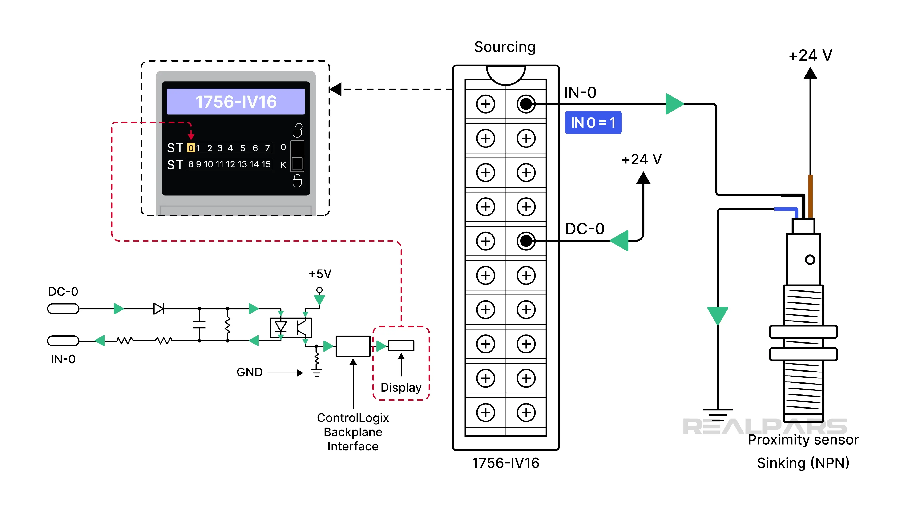
If LED 0 is off, the sinking input device output is effectively open, causing the input module to float, which the PLC program will interpret as a logic “0”.
If you decide to measure the input voltages for the ON and OFF LED states, don’t be fooled. They are the opposite of the sourcing sensor/sinking PLC input combination we discussed earlier. When the LED is on, the input voltage will be close to 0. When it is off, the input voltage will be about +24 volts.
According to the 1756-IV16 input specifications, an input voltage exceeding 5 volts will no longer be considered ON and will be recognized as OFF.
How can an input voltage rise above 5 volts when it appears to be grounded to zero through the sinking sensor? It’s often caused by high-resistance issues, such as corrosion at ground connection points or very long ground cable runs.
Wrap-Up
This is a good place to wrap up.
As we said earlier, the majority of PLC faults originate from field devices, I/O wiring, and occasionally the module. The PLC software itself is rarely at fault. LED indicators are undoubtedly helpful, but measuring the actual input voltage is the only reliable way to confirm what’s happening.
Understanding sinking and sourcing inputs and the expected voltage ranges on modules will take you a long way on your troubleshooting journey.