
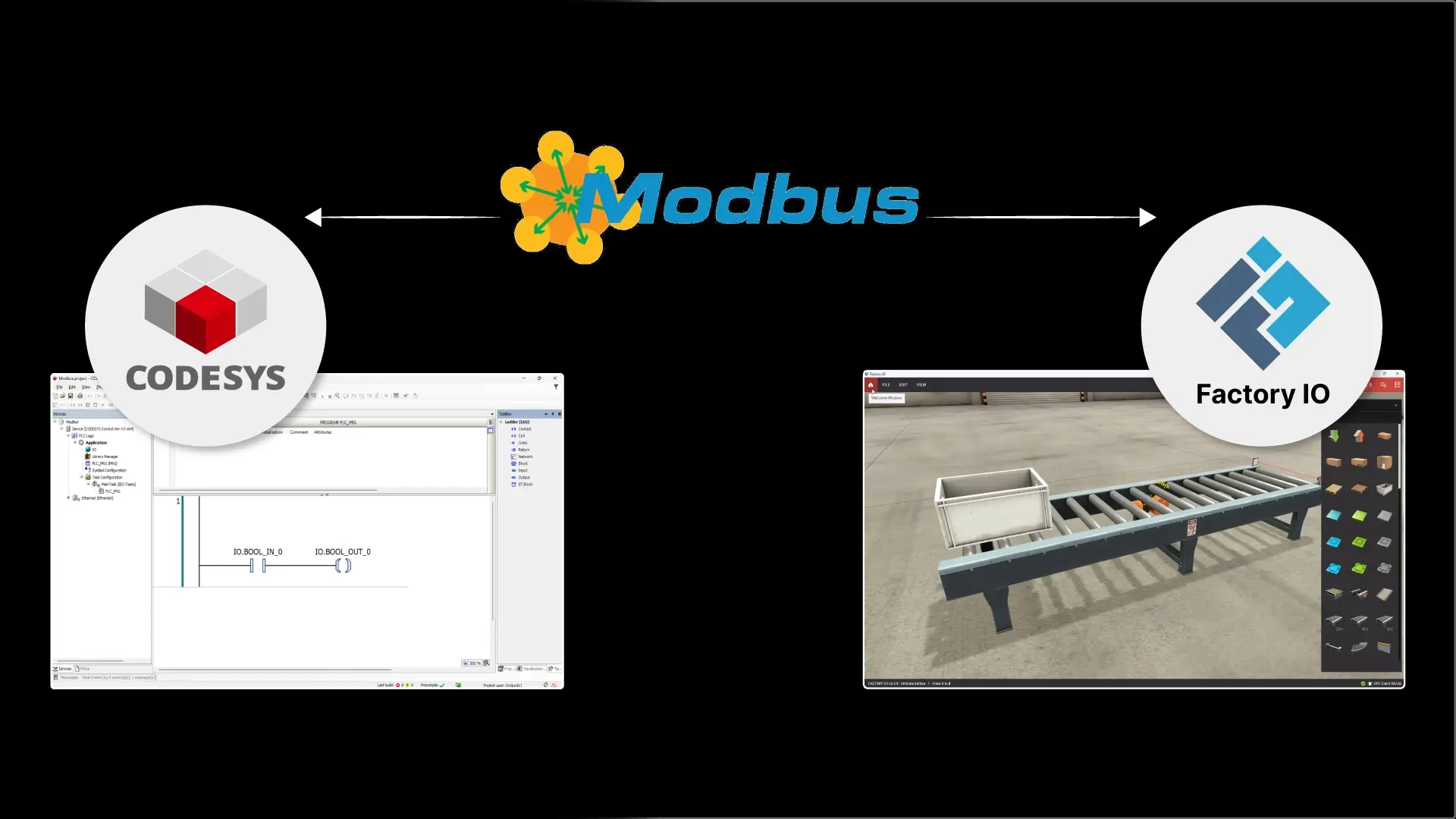
In this article, I’ll show you how to connect a CODESYS PLC to Factory IO using the Modbus communication protocol.
Before we learn how to connect CODESYS to Factory IO, let me take a minute to introduce the tools that we will use in this article.
CODESYS
CODESYS is a control runtime and development system.
The development system is completely free to download and use, making it a popular choice to learn PLC programming.
You can learn how to download and install CODESYS on your computer by checking out our blog post How to Download and Install CODESYS.
Factory IO
Factory IO is a 3D simulation environment for PLC training.
Using Factory IO, you can build virtual factories from a library of components and pre-built scenes. These virtual factories can be connected to a PLC to test and visualize how your code would control a physical process.
Factory IO is a powerful tool for learning PLC programming, and you can download a free trial of Factory IO using this link.
Modbus
Modbus is an industrial communication protocol that was created by Modicon, now Schneider Electric, in the late 1970s for PLC-to-PLC communication. Modbus is still widely used in industrial automation for connecting devices.
In this article, we’ll use Modbus TCP/IP to connect a Factory IO scene to a CODESYS PLC. This is a modern version of the Modbus communication protocol that sends data over Ethernet networks.
You can learn more about Modbus in our Modbus blog post.
Now that we’ve seen all of the tools that we’ll use in this article, let’s see how to connect a Factory IO scene to CODESYS using Modbus.
Use Modbus to connect a CODESYS PLC to Factory IO
Create a project
In CODESYS, I create a new project using the Standard project template and select CODESYS Control Win V3 as the device type and Ladder as the programming language for the PLC_PRG POU.
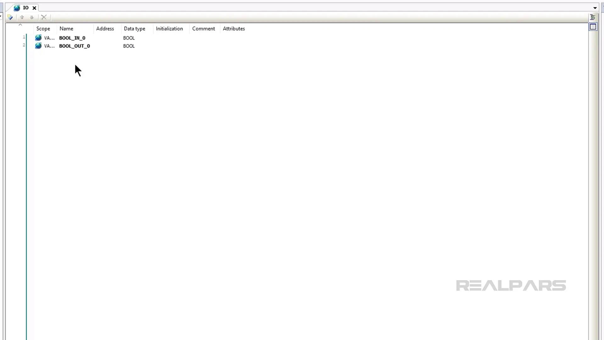
Configure variables
In the new project, I add a Global Variable list called IO and declare the variables that I will use in this project in the list.
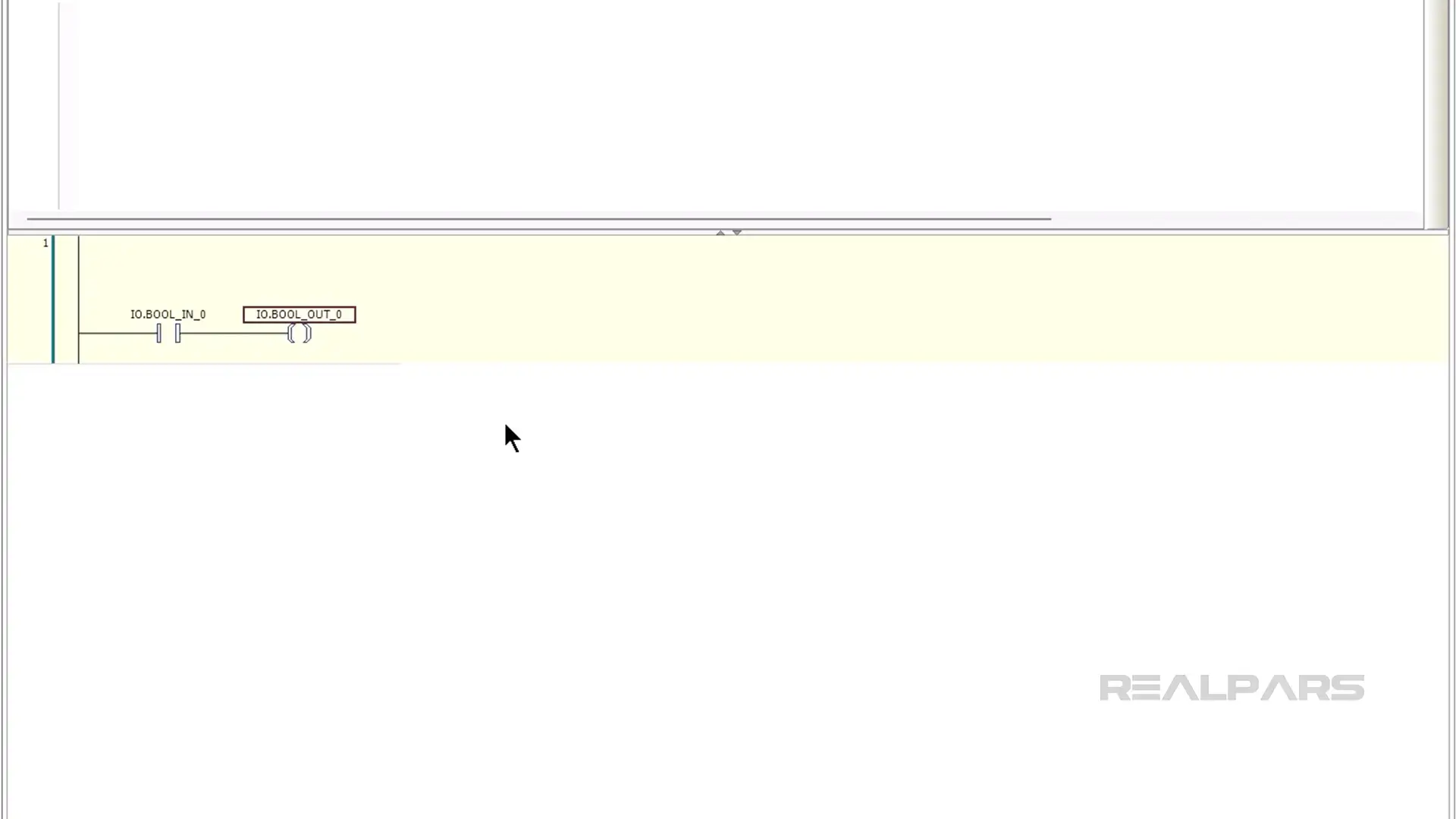
Write the logic
Next, I open up PLC_PRG and program the simple logic for this demo. In this case, the conveyor should run when the normally-closed sensor is not triggered.
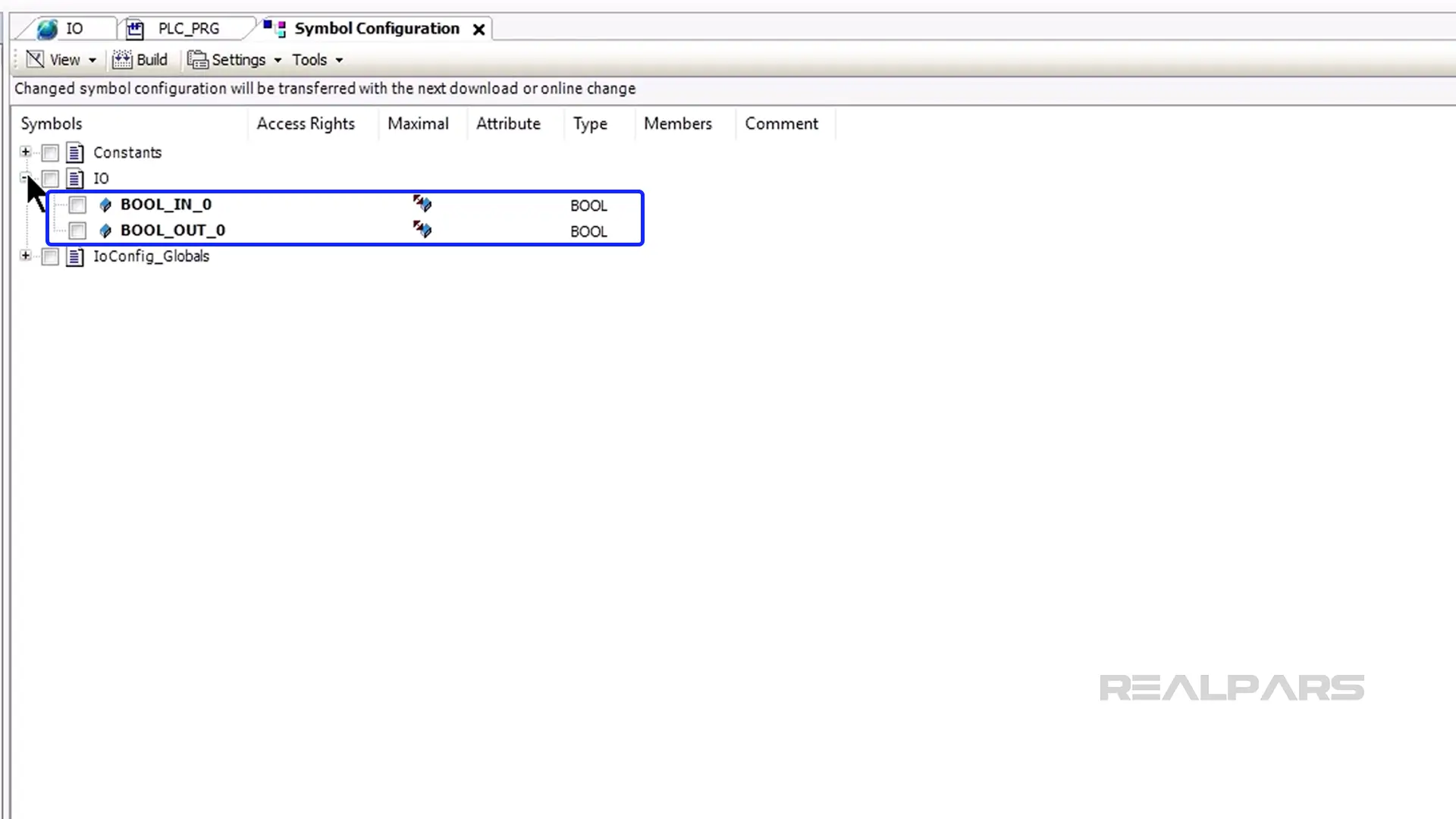
Add Symbol Configuration
Once the logic is written, I add a Symbol Configuration to the project.
Once the Symbol Configuration is added, I open it and press Build.
Once the project is built, the variables used in my project are listed in the Symbol Configuration.
Configure Modbus communication
Now that the data for the project is configured, we can configure the Modbus communication. I start by right-clicking on the Device and selecting Add Device.
From the list of fieldbuses, I expand Ethernet Adapter, select Ethernet, and click on Add Device.
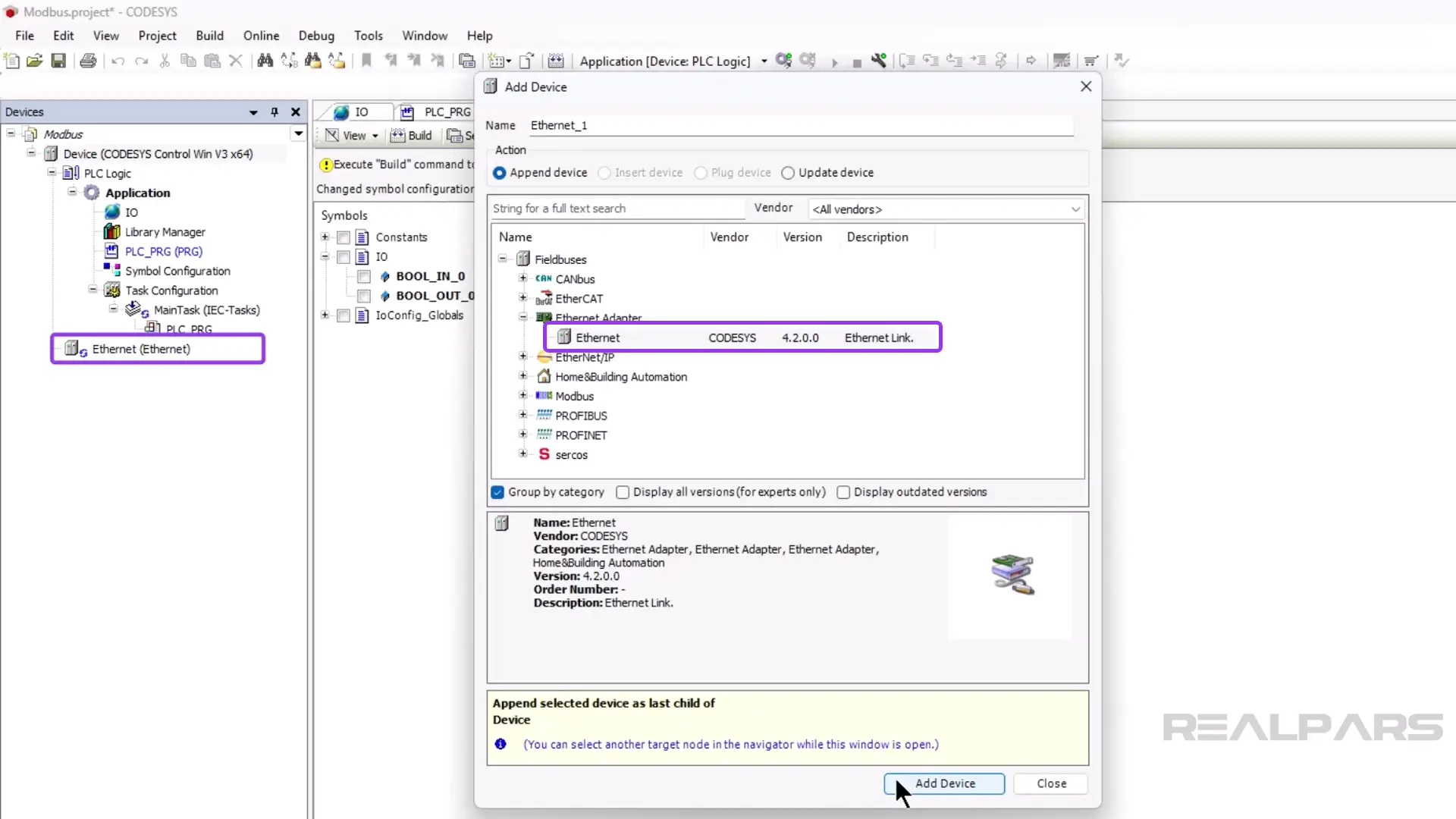
After adding the Ethernet adapter to the project, I close the Add Device dialog.
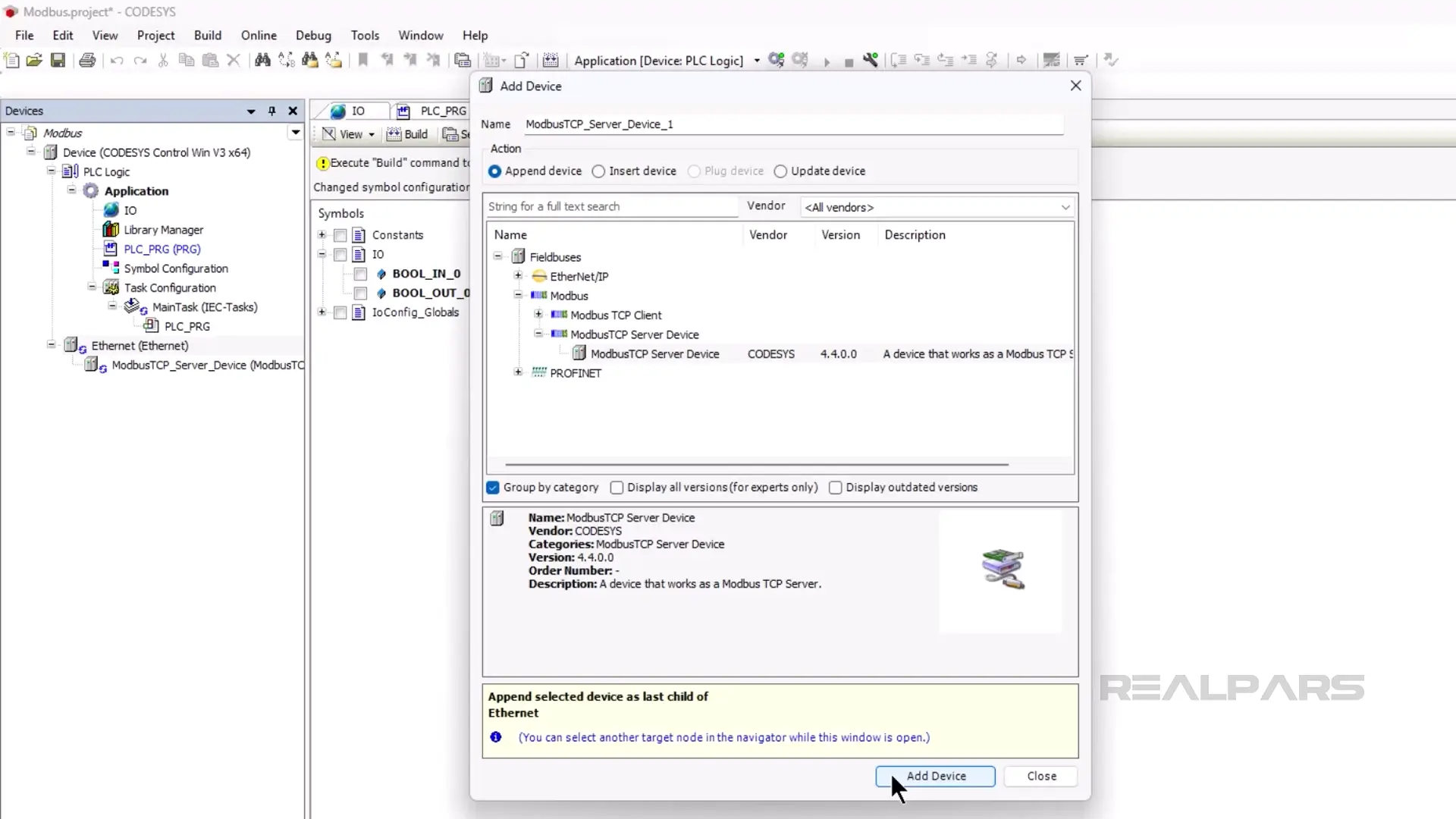
In the Devices tree, I right-click on the new Ethernet adapter and select Add Device.
In the Add Device dialog, I expand the Modbus folder and select ModbusTCP Server Device and click on Add Device.
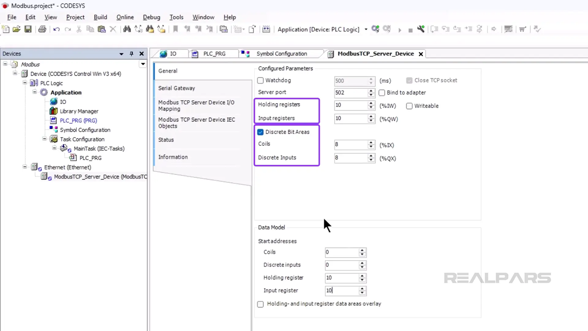
Now I can map the IO variables to the Modbus TCP Server. To do that, I close the Add Device dialog and double-click on the ModbusTCP Server Device in the device tree.
In the General tab, I specify that I want to enable Discrete Bit Areas and create 8 coils and discrete inputs.
I also update the addresses of the Holding and Input registers as shown here.
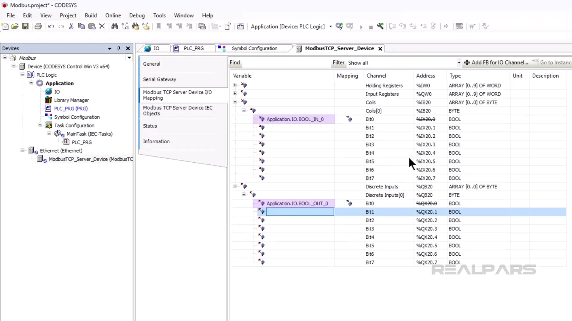
Next, I activate the Modbus TCP Server Device I/O Mapping and map the variables as shown here.
Download
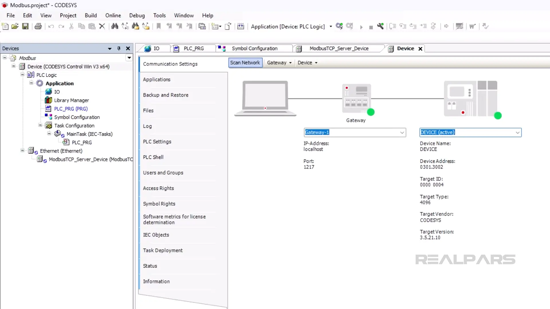
Finally, I start the CODESYS Control Win V3 runtime on my computer and set the communication path to the device as shown here.
With the communication path set, I can download to the device by clicking on Online and then Login.
Once the project is downloaded, I can start the PLC by clicking on Debug and then Start.
Set up Factory IO
Now that the CODESYS PLC is set up, I launch Factory IO and open the scene 1 - From A to B.
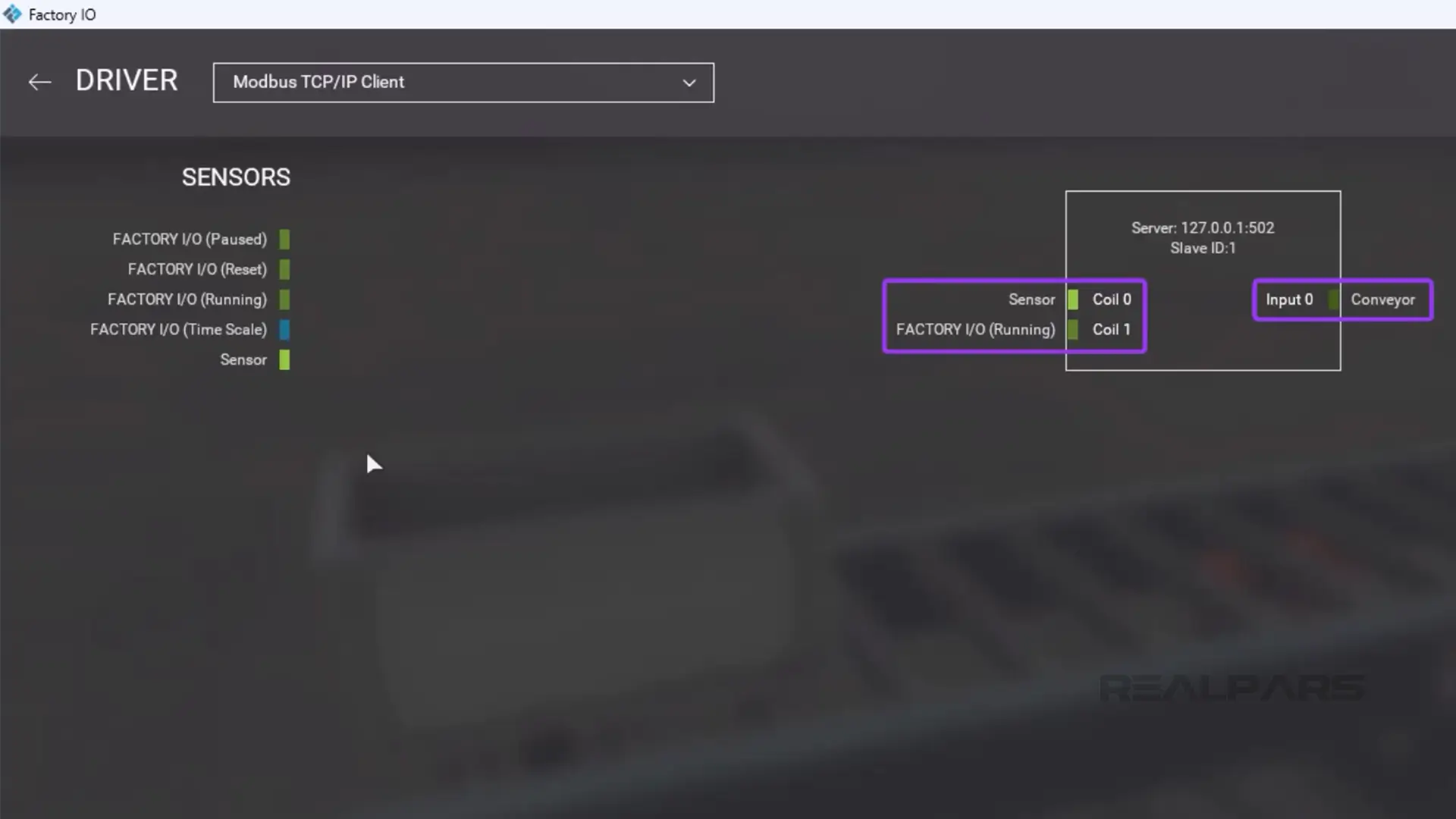
I open the Driver menu by clicking on File and then Drivers. In this window, I select Modbus TCP/IP Client from the dropdown list of available drivers.
As you can see, the tags are already mapped for us.
With the driver configured, I click Connect to connect Factory IO to the CODESYS PLC and close the Driver window.
Then I press the Play button to start the scene and verify that communications are working correctly.
Wrap-Up
In this article, I showed you how to connect a CODESYS PLC to Factory IO using the Modbus communication protocol. I also explained briefly what CODESYS, Factory IO, and Modbus are.
RealPars Business members get access to these courses and all of our other great courses for a fixed annual price. To learn more about how a RealPars Business membership can help train your team and reduce downtime, head to realpars.com/business.