

In the real world of the device to device process automation communication, a dialogue or conversation between devices occurs systematically, in many cases, over different types of communication networks and in different languages.
Modbus as an “Open Protocol”
Depending on the process automation equipment manufacturer, a very specific or proprietary language is used or it may be a language that is commonly open to the industry. It is these open protocols many manufacturers adapt to easily integrate their products in a market.

An “Open protocol” means the specifications are published and may be used by anyone freely or by license.
Open protocols are usually backed by a combination of corporations, user groups, professional societies, and governments. This provides users with a much wider choice of devices or systems that can be utilized to meet specific applications.
Advantages of open protocols include support by multiple manufacturers, software vendors, and install or service organizations, active community groups for support, the ability to stay current and add capabilities in the future.
One of the most common Automation Communication Protocols of connecting industrial electronic devices used today is Modbus.
In this article, we will discuss what Modbus communication protocol is and the types of Modbus communication used in the industry.
What is Modbus?
The Modbus communication protocol is the oldest and by far the most popular automation protocol in the field of process automation and SCADA (Supervisory Control and Data Acquisition).

Knowing how to create Modbus based networks is essential for any electrical technician and engineer working in these occupation fields.
Being able to integrate devices from different manufacturers is a skill that is in demand and will ultimately make you more valuable and marketable in the industry.
Modbus is a communications protocol published by Modicon in 1979 for use with its Programmable Logic Controllers (PLCs). Modicon is now owned by Schneider Electric.
Modbus provides a common language for devices and equipment to communicate with one and another.
For example, Modbus enables devices on a system that measures temperature and humidity connected on the same network to communicate the results to a supervisory computer or PLC.

The development and update of Modbus protocols have been managed by the Modbus Organization. The Modbus Organization is an association of users and suppliers of Modbus-compliant devices.
Types of Modbus Communication Protocol
Several versions of the Modbus protocol exist for the serial port and Ethernet and the most common are:
– Modbus RTU
– Modbus ASCII
– Modbus TCP
– Modbus Plus

Modicon published the Modbus communication interface for a multidrop network based on a Master-Slave architecture.
Communication between the Modbus nodes is achieved with send request and read response type messages.
Modbus Protocol and its Physical Media
Modbus is an open standard that describes the messaging communication dialog.
Modbus communicates over several types of physical media such as:
– Serial RS-232
– Serial RS-485
– Serial RS-422
– Ethernet

The original Modbus interface ran on RS-232 serial communication, but most of the later Modbus implementations use RS-485 because it allowed:
– Longer distances.
– Higher speeds.
– The possibility of multiple devices on a single multi-drop network.

Master-Slave Modbus communication over serial RS-485 physical media using two-wire transmit and receive connections.

On simple interfaces like RS232 or RS485, the Modbus messages are sent in plain form over the network and the network will be dedicated to only Modbus communication.
However, if your network requires multiple heterogeneous devices using a more versatile network system like TCP/IP over Ethernet, the Modbus messages are embedded in Ethernet packets with the format prescribed for this physical interface.
So in this case, Modbus and other types of mixed protocols can co-exist at the same physical interface at the same time.

Introduction to Modbus Message Structure
The main Modbus message structure is Peer-to-Peer. Modbus is able to function on both Point-to-Point and Multidrop networks.

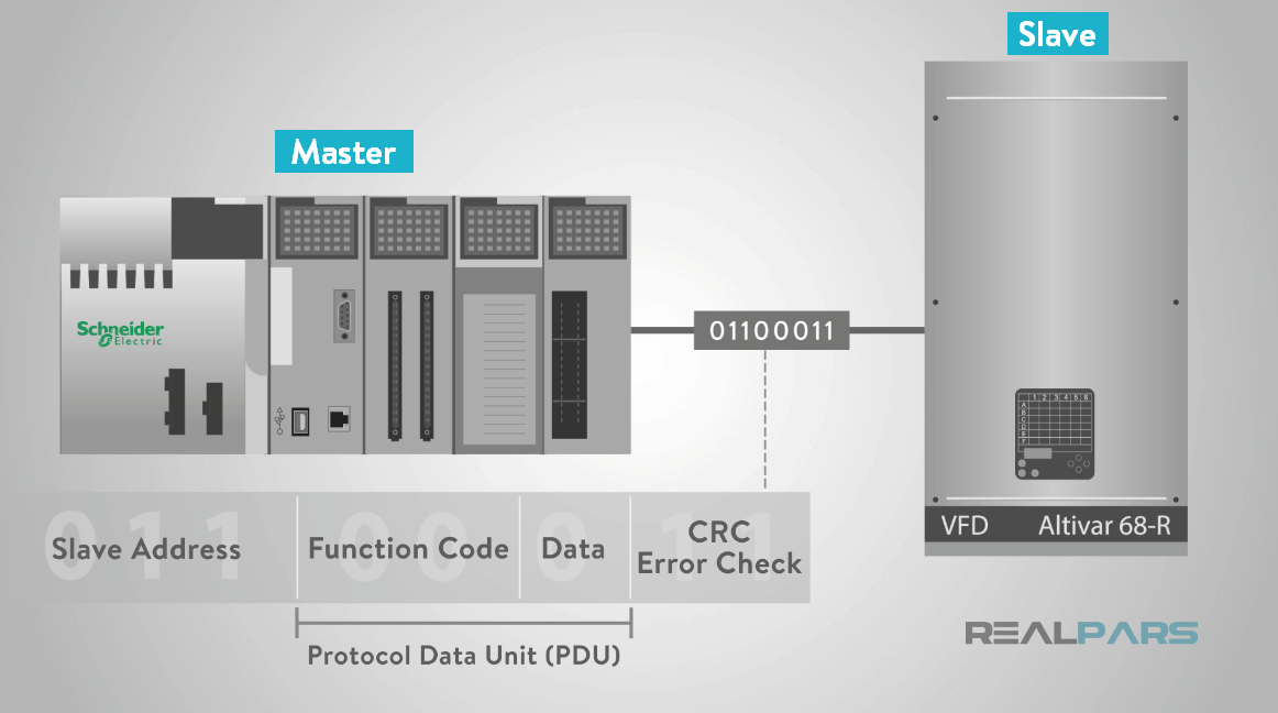
So how does Modbus work? Each Modbus message has the same structure. Four basic elements are present in each message. The sequence and order of these elements are the same for all messages. This allows for easy parsing of the content of the Modbus message.
Modbus devices communicate using a Master-Slave (Client-Server for Ethernet) technique in which only one device (the Master/Server) can initiate transactions (called queries).
The other devices (Slaves/Clients) respond by supplying the requested data to the master, or by taking the action requested in the query.
A slave is any peripheral device such as an I/O transducer, valve, network drive, or other measuring types of devices which processes information and sends its response message to the master using Modbus.
Masters can address individual slaves or initiate a broadcast message to all slaves. Slaves return a response to all message queries addressed to them individually, but do not respond to broadcast messages.
Slaves do not initiate messages on their own and only respond to message queries transmitted from the master.
Modbus functions perform read and write instructions to the slave’s internal memory registers to configure, monitor, and control the slave’s inputs and outputs.

The master’s query will consist of:
– Slave address (broadcast address).
– Function code with a read or write data command to the slave.
– The write command “Data” if a write command was initiated by the master.
– Error checking field.
The error checking is a value the master or slave creates at the beginning of the transmission or response and then checked when the message is received to verify the contents are correct.

A slave’s response consists of:
– Fields confirming it received the request.
– The data to be returned.
– Error checking data.
If no error occurs, the slave’s response contains the data as requested.
If an error occurs in the message query received by the slave, or if the slave is unable to perform the action requested, the slave will return an exception message as its response.

The error check field of the slave’s message frame allows the master to confirm that the contents of the message are valid.

Modbus Protocol Devices
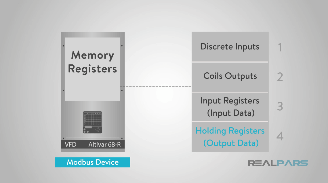
Modbus protocol devices will typically include a register map outlining where the configuration, input and output data can be written and read from. You should always refer to the slave’s register map of your device to gain a better understanding of its overall operation.
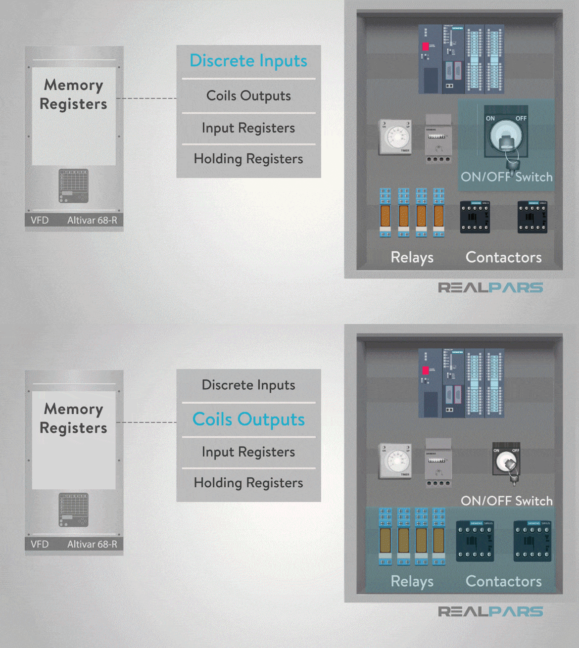
The Modbus data model has a simple structure described in four basic data types:
- Discrete Inputs
- Coils Outputs
- Input Registers (Input Data)
- Holding Registers (Output Data)
Modbus Protocol Data Unit (PDU)
When it comes to how Modbus works, the service request area of the message or Modbus Protocol Data Unit or PDU is comprised of
– Function code.
– A number of “data” bytes requested by the master.
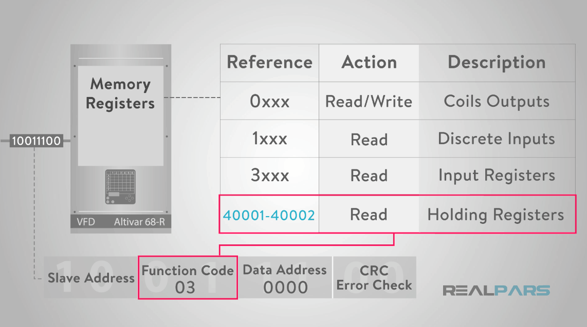
The Modbus memory registers of a device are organized around the four basic data reference types and this data type is further identified by the leading number used in the devices memory address, such as:
– Zero (0) based register referencing a message to Read or Write “discrete outputs or coils”.
– One (1) based register referencing Reading “discrete inputs”.
– Three (3) based register referencing Reading “input registers”.
– Four (4) based register referencing Reading or Writing to “output or holding registers”.
Modbus Message: Function Code Field
The “function code field” specifies which register data group it reads or writes to and from the slave.
For example, a Function code 03, read Holding Registers 40001-40002 is addressed as data register 0000 in the data address field of the message sent to the slave.
The function code 03 works on Holding Register type (4xxxx) in the slave’s data map because the request specifies using a holding register data type operation and the 4xxxx addressing in the request is implied.
The fields in the PDU are broken down into bytes and grouped by the field name.
The request message contains:
– The “Slave address” of 01.
– The “Function code” of 03 (Read from Holding Registers 4xxxx).
– The “starting address” HI and LO bytes (0000) which specifies the “starting register”.
– The “count number of addresses” to read from the slave, register HI and LO bytes of the count value (0002) which specifies the “quantity of registers” to be read from the slave.
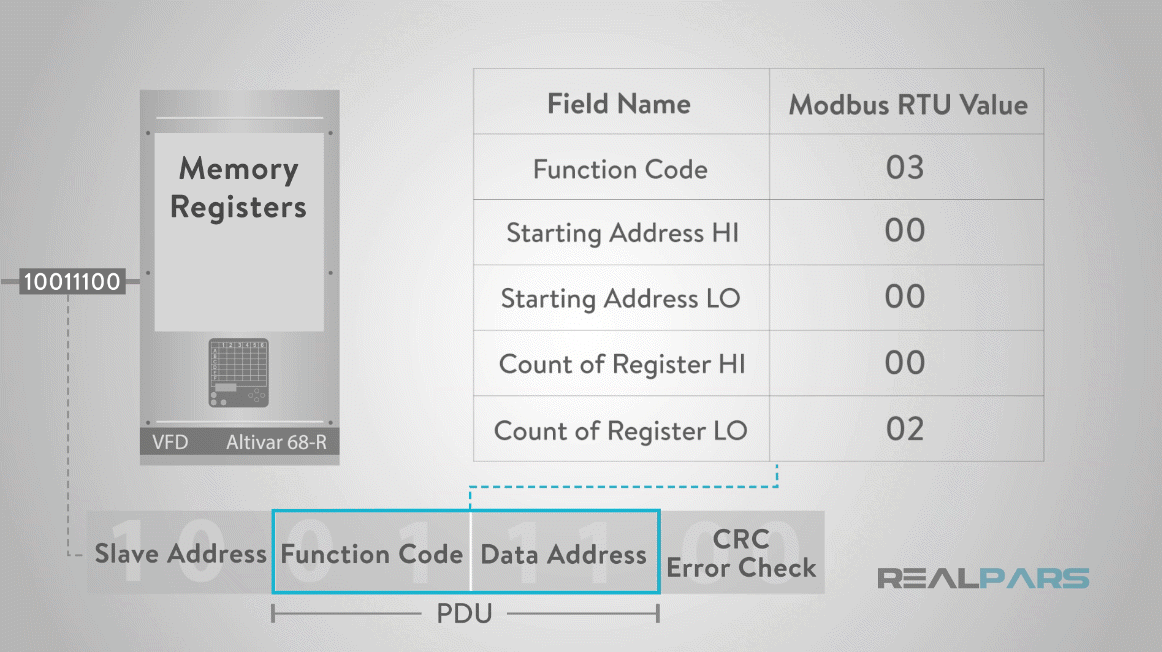
Example of a request to “read” the “first two registers” in the “Holding Register” area 0 to 1 (register 40001 to 40002) from slave device 1 is shown below.
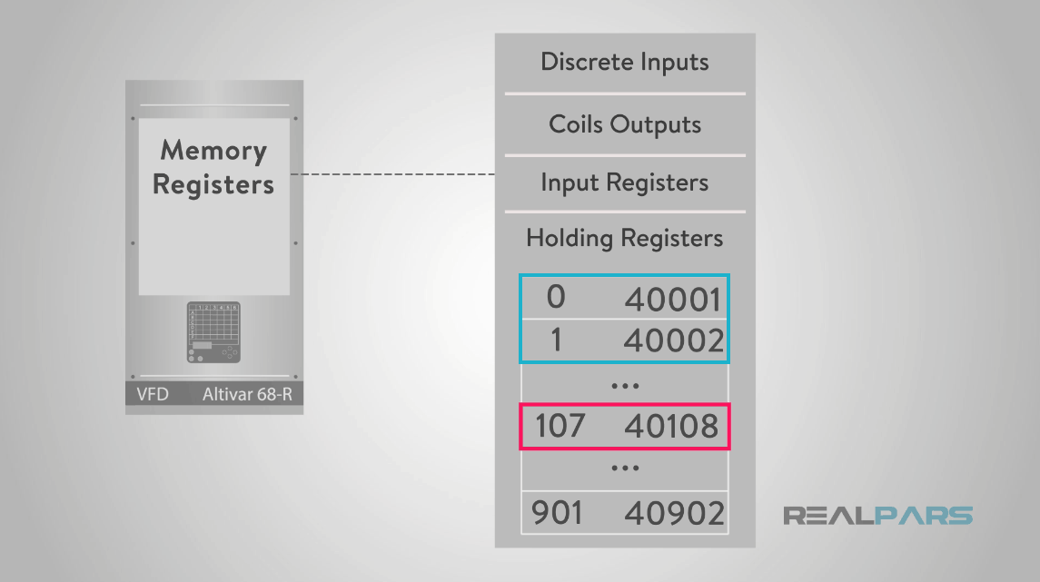
It is revealed in the above picture that the holding register 40108 is actually addressed as register 107 in the message data area of the PDU.
Many of the data types are named from its use; for example, a single-bit physical output is called a coil, and a single-bit physical input is called a discrete input or a contact.
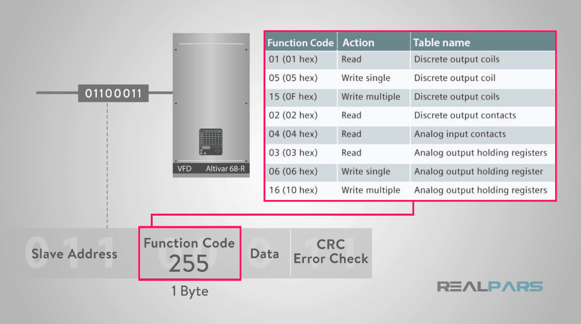
The function code field of the message will contain one byte that tells the slave what kind of action to take.
Valid function codes are range from 1 to 255, but not all codes will apply to a particular slave.
The table shown in the below picture highlights a subset of standard Modbus protocol functions.
Modbus Message: Data Field
In addition, the master request “data” field, provides the slave with any additional information required by the slave to complete the action specified by the “function code” in the master’s request.
The master’s request typically includes:
– The slave map register address.
– The number of registers to provide in the request.
– Any write data from the master.
Modbus Message Error Handling
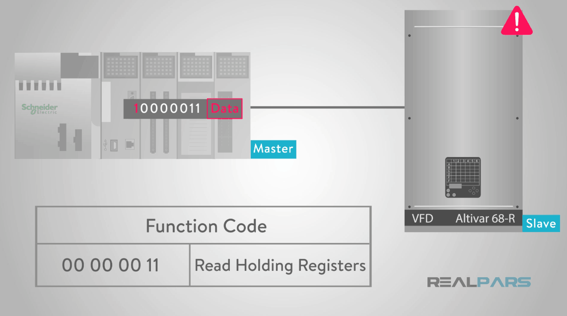
The slave’s normal response simply echoes the original function code of the request, but the slave’s error response returns a code that is equivalent to the original function code with the most significant bit set to logic 1.
For example, the “Read Holding Registers” command (Function Code 03) has the function code with 1 byte containing 8 bits is binary 0000 0011 (03 Hex). If the slave device accepts the request without error it will return the same code in its response.
However, if an error occurs, the slave will return 1 byte containing 8 binary bits 1000 0011 (the most significant bit set to logic 1) in the “function code” field and appends a unique code (Exception Code) in the “data” field of the response message that tells the master device what kind of error occurred, or the reason for the error.
Modbus RTU Most Common Function Codes
This function code 01, “Read Coils” code, is used to read from 1 to 2000 contiguous registers for the status of coils in a slave device. The Request PDU specifies the first coil address of the slave’s memory registers, and the number of coils to read from the slave device.
The function code 02, “Read Discrete Input” code, is used to read from 1 to 2000 contiguous status of discrete outputs in a remote slave. The Request PDU specifies the first input address of the slave’s memory registers, and the number of inputs to read from the slave device.
The function code 03, “Read Holding Registers” code, is used to read the contents of a contiguous block of holding registers in a remote slave. The Request PDU specifies the starting register address and the number of registers to read from the slave device.
The function code 04, “Read Input Registers” code, is used to read from 1 to 125 contiguous input registers in a remote device. The Request PDU specifies the starting register address and the number of registers.
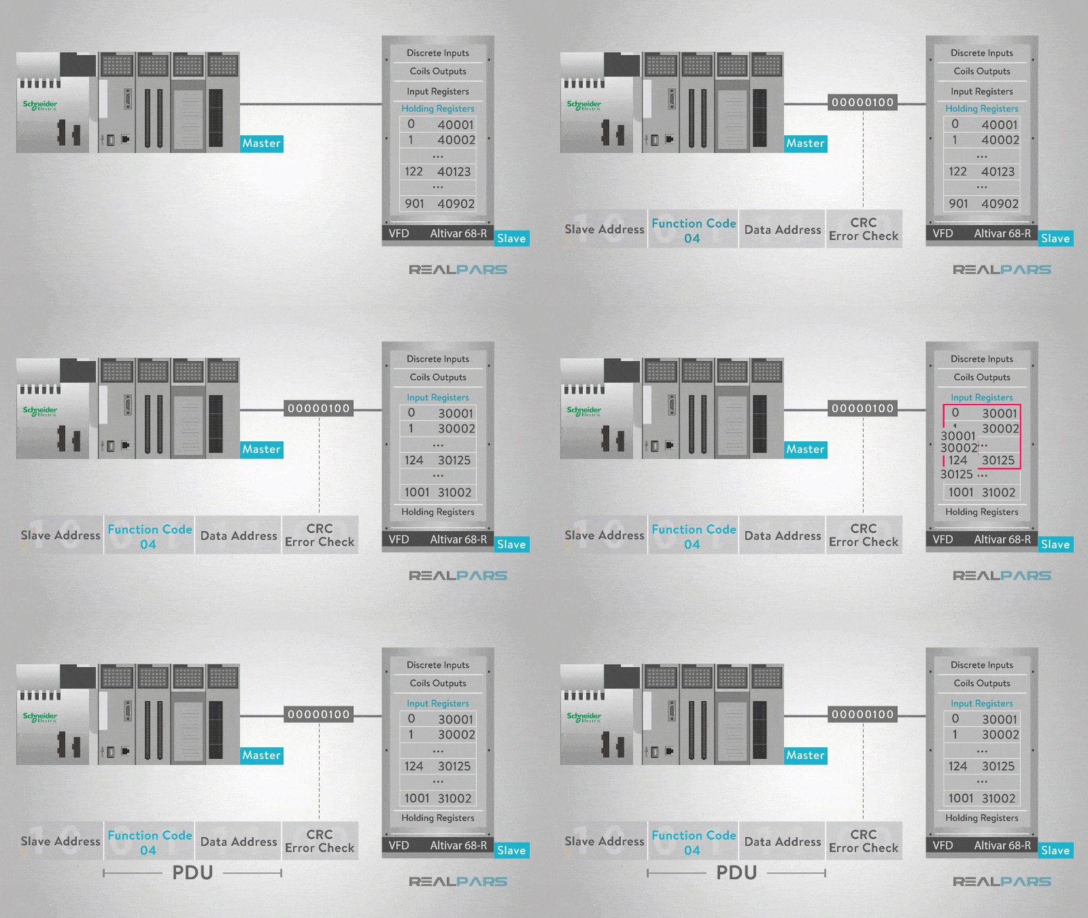
The function code 05, “Write Single Coil” code, is used to write a single output to either ON or OFF in a remote slave device.
The function code 06, “Write Single Register” code, is used to write a single holding register in a remote slave device. The Request PDU specifies the address of the slave memory register address to be written to.
The function code 15, “Write Multiple Coils” code, is used to force each coil in a sequence of coils to either ON or OFF in a remote slave device. The Request PDU specifies the coils memory address to be forced ON or OFF.
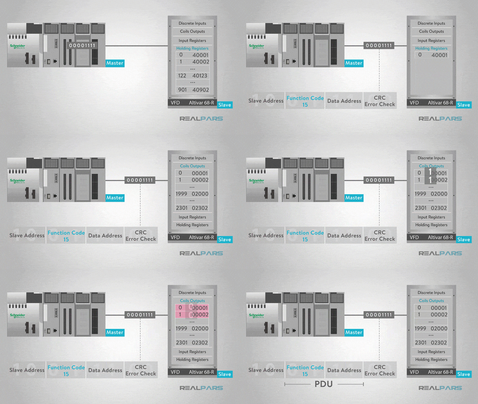
And the function code 16, “Write Multiple Registers” is used to write a block of contiguous registers from 1 to 123 registers in a remote slave device.
While these Modbus function codes represent the most common read and write functions, it would be helpful for you to review the Modbus protocol specificationfor additional information.
And for more information about different protocols used with automation, refer to this web page.
Wrap-Up
In this article, you learned about what Modbus communication protocol is and the types of Modbus communication used in the industry.
What’s the biggest “aha” you’re taking away from this technical conversation? How can you put that insight into action now? Tell us the comments below.
Thanks again for reading. Leave your questions and comments and we’ll chat with you soon!
Happy learning,
The RealPars Team

