
It’s challenging to find an industry that doesn't incorporate temperature measurement, as almost every chemical/physical process depends on controlling heat. The Resistance Temperature Detector, or RTD, is a rugged and versatile sensor used to detect temperature.
Watch the video below to learn more about this topic in a clear and easy way.
In this article, we will begin with a brief overview of how an RTD works, its designation, and why it often has more than two leads. We’ll introduce you to the two methods of integrating an RTD with a PLC analog input and explain the pros and cons of each.
We will take you through a step-by-step demonstration of how to configure an RTD with a 2-wire Transmitter connected to a ControlLogix 1756-IF8 analog input module using Studio 5000.
To make this demonstration easier to understand, we will use a ControlLogix Simulation program to create analog input values.
Finally, we will demonstrate how to utilize the 1756-IF8 module's scaled values in Ladder Logic to activate an alarm at a specific temperature.
RTD basics
Okay, let's start with a bit of background on the RTD.
The RTD is a simple device. In the early 1800s, scientists discovered that the resistance of metals like copper and platinum changes with temperature, making them ideal for precise temperature measurements.
In the 1980s, the Pt100 RTD was standardized as an industrial RTD and remains the most widely used in process control today.
Let’s break down the designation Pt100. Pt is platinum, and 100 is the RTD’s ohm value at zero degrees Centigrade.
To determine the measurement temperature, the RTD is excited by either a voltage or a current source.
Most RTDs used in process control have three or four wires to compensate for the length of the leads.
RTD and PLC analog input integration
There are two methods of integrating an RTD with a PLC analog input. The first method utilizes an application-specific analog input module such as the AB 1756-IR12. This module connects directly to the RTD under test.
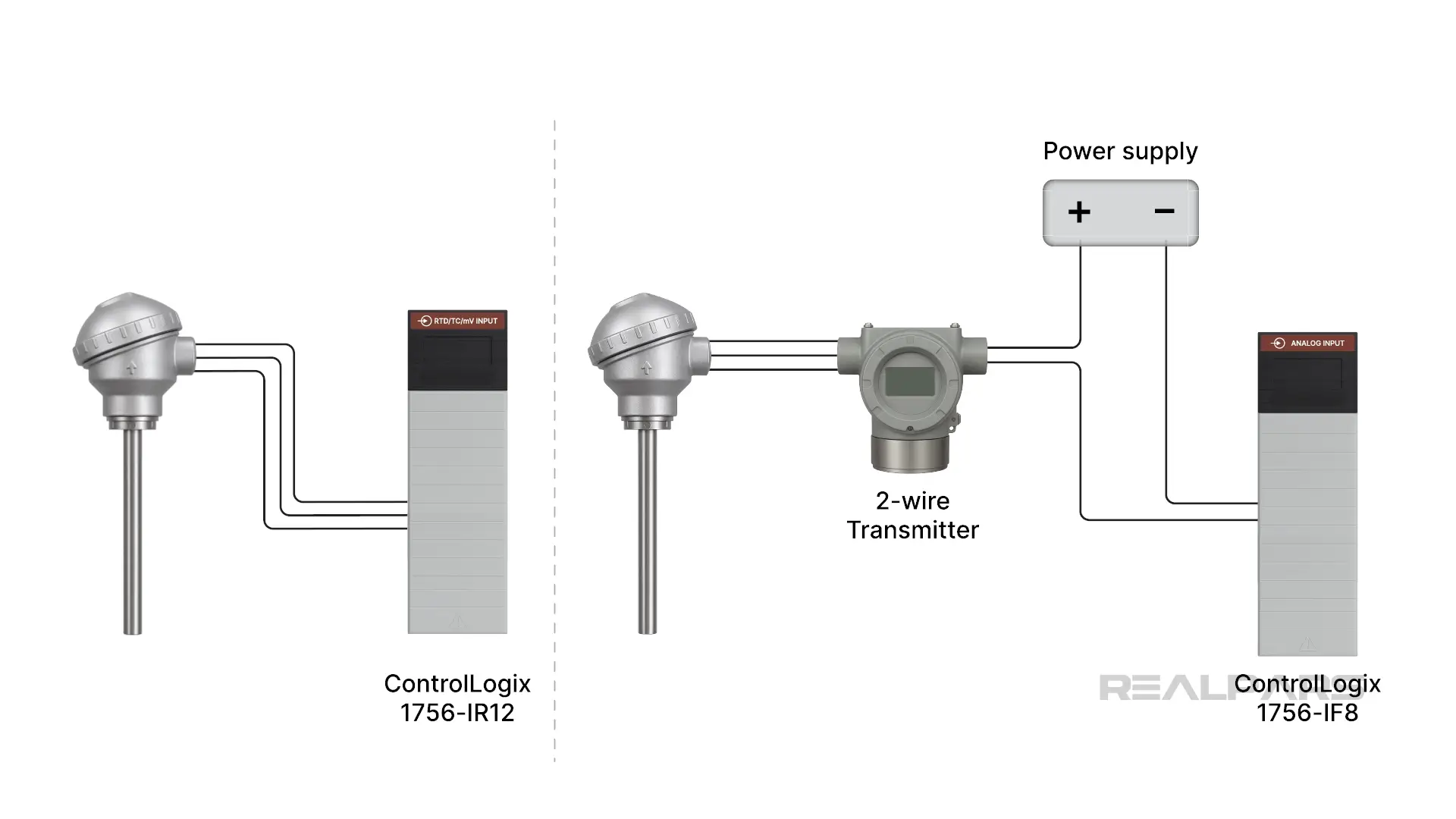
The second method utilizes a two-wire, 4-20 mA temperature transmitter connected to a generic analog input module such as the AB 1756-IF8.
Both methods ultimately provide an accurate, scaled temperature reading inside the PLC.
Of course, there are pros and cons to each. You are more likely to find RTDs connected directly to an input module if the RTD is close to the PLC and the wiring is short.
Using a 4-20 mA transmitter provides a more flexible environment, as the receiving input module can be used in other control loops as well.
That is the last time you will hear about the direct-to-PLC input module method, as we are going to do a deep dive into configuring an RTD with a 2-wire Transmitter connected to a ControlLogix 1756-IF8 analog input module.
Analog input module configuration
We’ll start with a typical setup, featuring a 3-wire Pt100 RTD connected to a two-wire transmitter that is providing a 4-20 mA process variable signal to an AB 1756-IF8 analog input module.
We’ve already performed I/O module configuration in the ControlLogix Simulation program. We have nine slots in our virtual PLC. We will simulate the transmitter connected to the AB 1756-IF8 module in Slot 7, Channel 1.
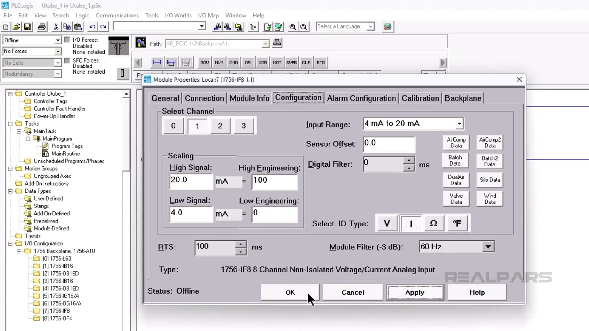
Opening the Configuration properties for this module shows 4 channels to choose from.
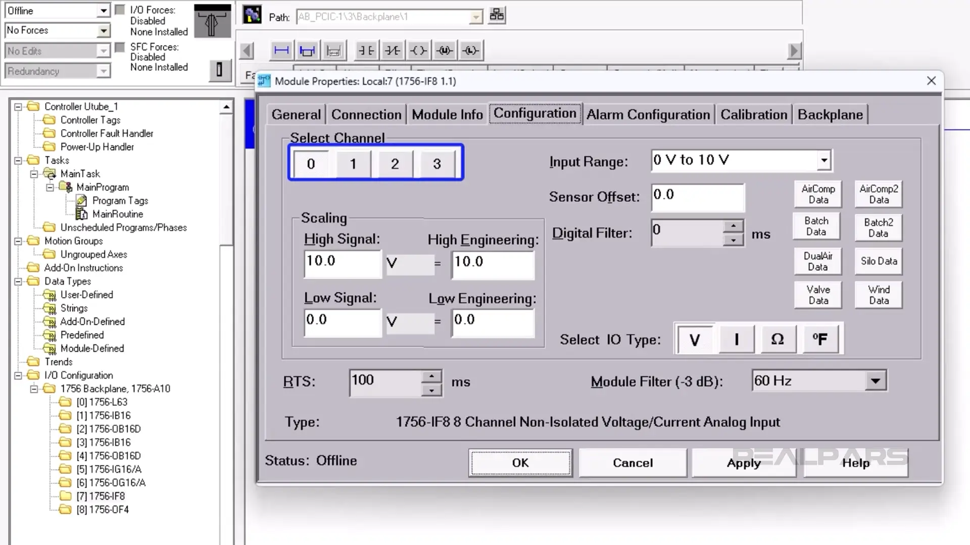
Each channel is capable of receiving a voltage or current input range.
The views differ in RS Logix 5000 and Studio 5000 from those in our simulation software.
We’re going to focus on the Scaling section. That’s where we will scale the input signal from the temperature transmitter into values we can use in our PLC ladder logic program.
Creating the Ladder Logic routine
Let’s write a simple routine to move the data from the analog input module in Slot 7, Channel 1. Remember, our 4 to 20 mA transmitter is connected to this module.
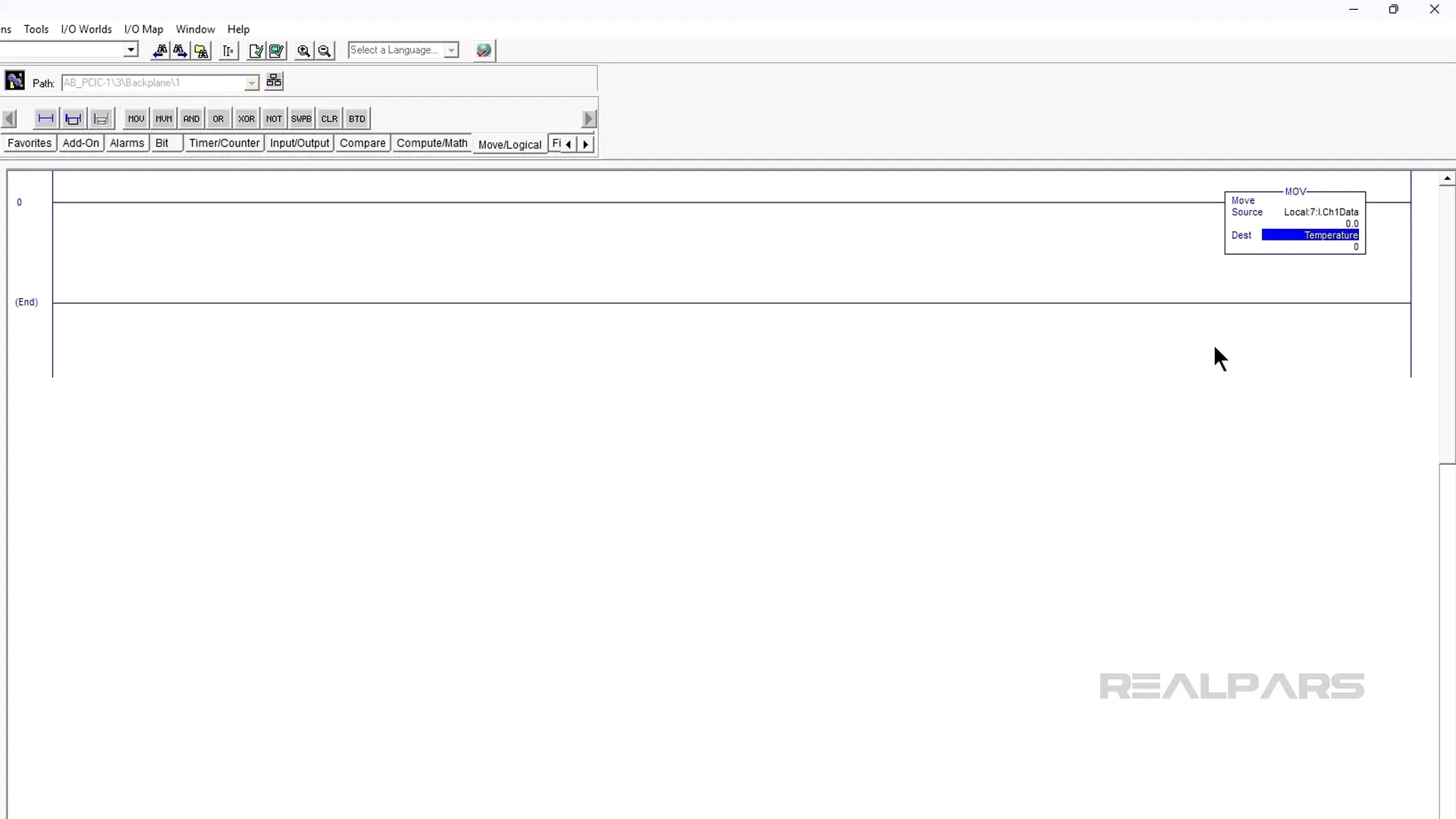
We start by placing a MOV instruction on Rung 0.
The MOV instruction Source will be the data from the analog input module.
We’ll create a new Base Tag called Temperature for the Destination.
We select REAL as the Data type.
And we will name it Temperature.
Next, we will assign Local:7:I.Ch1Data from the dropdown list as the MOV Source. This is the data from our temperature transmitter.
And now we assign Temperature as the MOV instruction Destination.
Let’s assume our process variable temperature range is 0 to 100 degrees Centigrade.
Our transmitter output range of 4 to 20 mA, therefore, corresponds to a temperature range of 0 to 100 degrees Centigrade.
Ok, now let’s go back to the 1756-IF8 properties and configure the scaling to accurately represent our process variable temperature range.
Choose Channel 1, and an input range of 4 to 20 mA.
The High Signal and Low Signal values are directly related to the input signal.
In our case, our high signal is 20 mA, and our low signal is 4 mA.
High and Low Engineering have no units until you decide.
You can call them bananas if you like.
We will use degrees Centigrade as our units.
We set the High Engineering value to 100, and the low engineering value to zero.
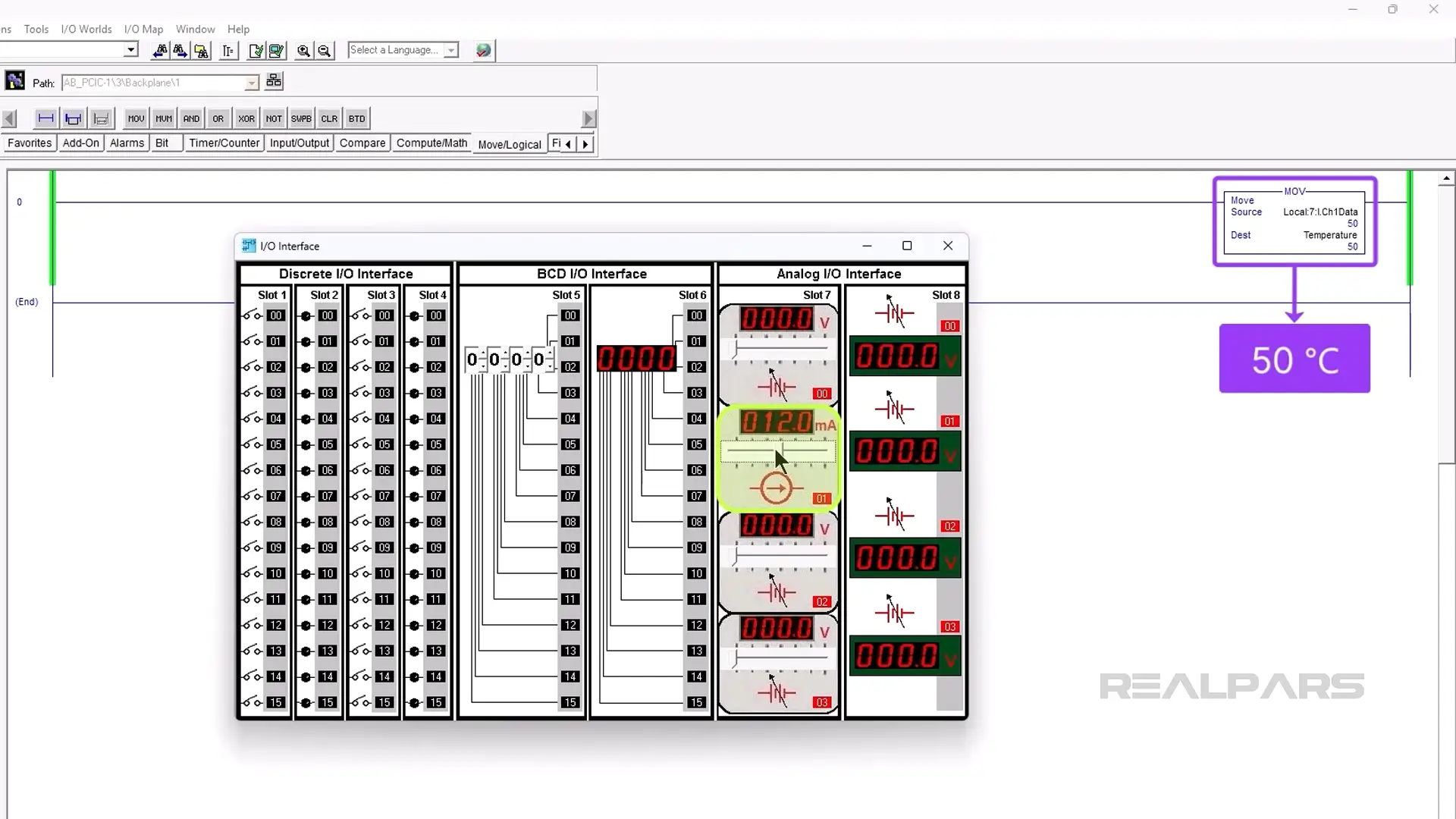
Let’s run the ladder logic routine and simulate the temperature using the built-in simulator.
The MOV Instruction Source and Destination values change between 0 and 100 as we adjust the Slot 7, Channel 1 slider for current values ranging from 4 to 20 mA.
Setting the input value to 12 mA produces a corresponding Destination value of 50, which translates to a Temperature of 50 degrees Celsius. It’s that simple!
Changing the temperature range
Let’s change the temperature range to 40 Degrees Celsius to 140 degrees Celsius. All we have to do is change the High Engineering Scaling value to 140 and the low engineering value to 40.
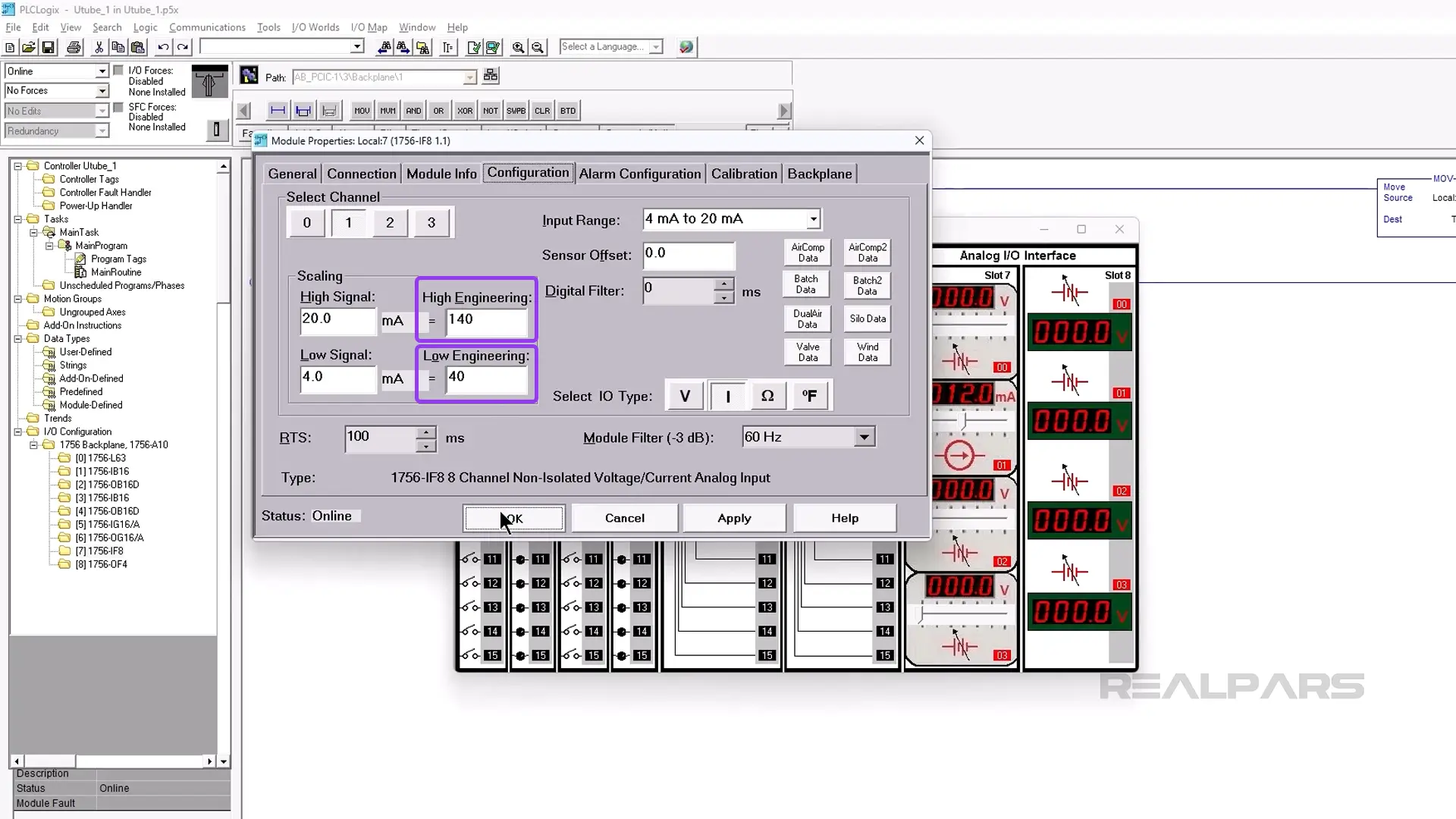
This time, the MOV Destination value representing Temperature changes from 40 to 140 as we change the current slider from 4 to 20 mA.
Adding a high-temperature alarm
There are many things we can do with this Temperature value.
Let’s add another ladder rung and code to trigger a high-temperature alarm if the temperature exceeds 90 percent.
Performing a few math calculations, we find that the 90% point between 40℃ and 140℃ is 130℃.
If you are fuzzy on how we got the 90% temperature value, we recommend reading the article Temperature Transmitter Explained | Connection and Calibration.
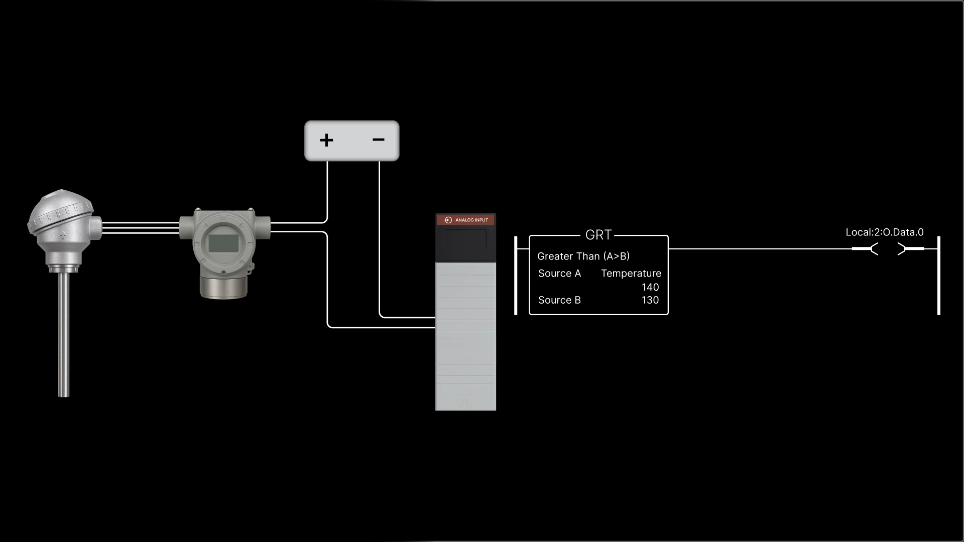
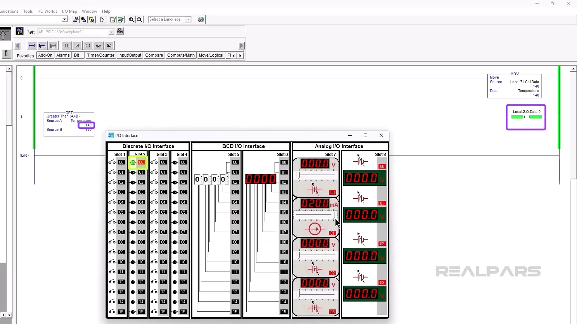
We add another rung and insert the GRT Compare instruction. We’ll use this instruction to compare the temperature with our alarm point of 130℃.
An OTE is added to activate our alarm.
We choose Temperature from the dropdown list as Source A. For Source B, we enter 130.
Our simulator has a digital output module in Slot 2. We will use one of the outputs for our alarm.
Next, we create a new controller alias tag called High_Temperature. This is a BOOL aliased to the digital output card in Slot 2, output 0.
And finally, we address the High_Temperature OTE as Local:2:O.Data.0 from the dropdown menu.
Okay, let's try it. If our current input slider exceeds 90% or 130℃, the OTE goes True, and the Lamp connected to Slot 2, output zero turns on.
Conclusion
Ok, that’s it for this article.
We hope we’ve convinced you that with some basic scaling, an RTD signal can be translated into ladder logic that you can use for accurate temperature monitoring and control.
If unplanned downtime keeps slowing your lines, RealPars Business can give your team the skills to solve issues faster. Learn more about RealPars Business by visiting realpars.com/business.