
Timers are very important instructions in PLC programming that are used to delay signals turning on or off.
In this article, I will introduce you to the concept of timers in PLC programming and explain the specific timer instructions that are available for the Ladder Diagram programming language in Studio 5000 Logix Designer.
Timer concepts
As I mentioned in the introduction, timers are used in PLC programming to delay a signal turning on or off. Before we look specifically at how the different timer instructions in Studio 5000 Logix Designer work, let’s look quickly at how timers work in general.
In a Delay On Timer, which is one of the most commonly used types of timers in PLC programming, the timer starts accumulating timer when the timer is enabled.
While the timer is enabled, the accumulated time of the timer is updated every scan.
When the accumulated time equals the preset time, which is defined by the PLC programmer, the timer is done, and the timer’s output turns on.
When the timer’s input turns off, the timer’s output turns off, and the accumulated time is reset.
You can see how you could use a timer instruction to delay turning on an input for a pre-defined time after an input turns on.
Now that you know how timers work in PLC programming in general, let’s look at the specific timer instructions that are available for the Ladder Diagram programming language in Studio 5000 Logix Designer.
Timers in Studio 5000 Logix Designer
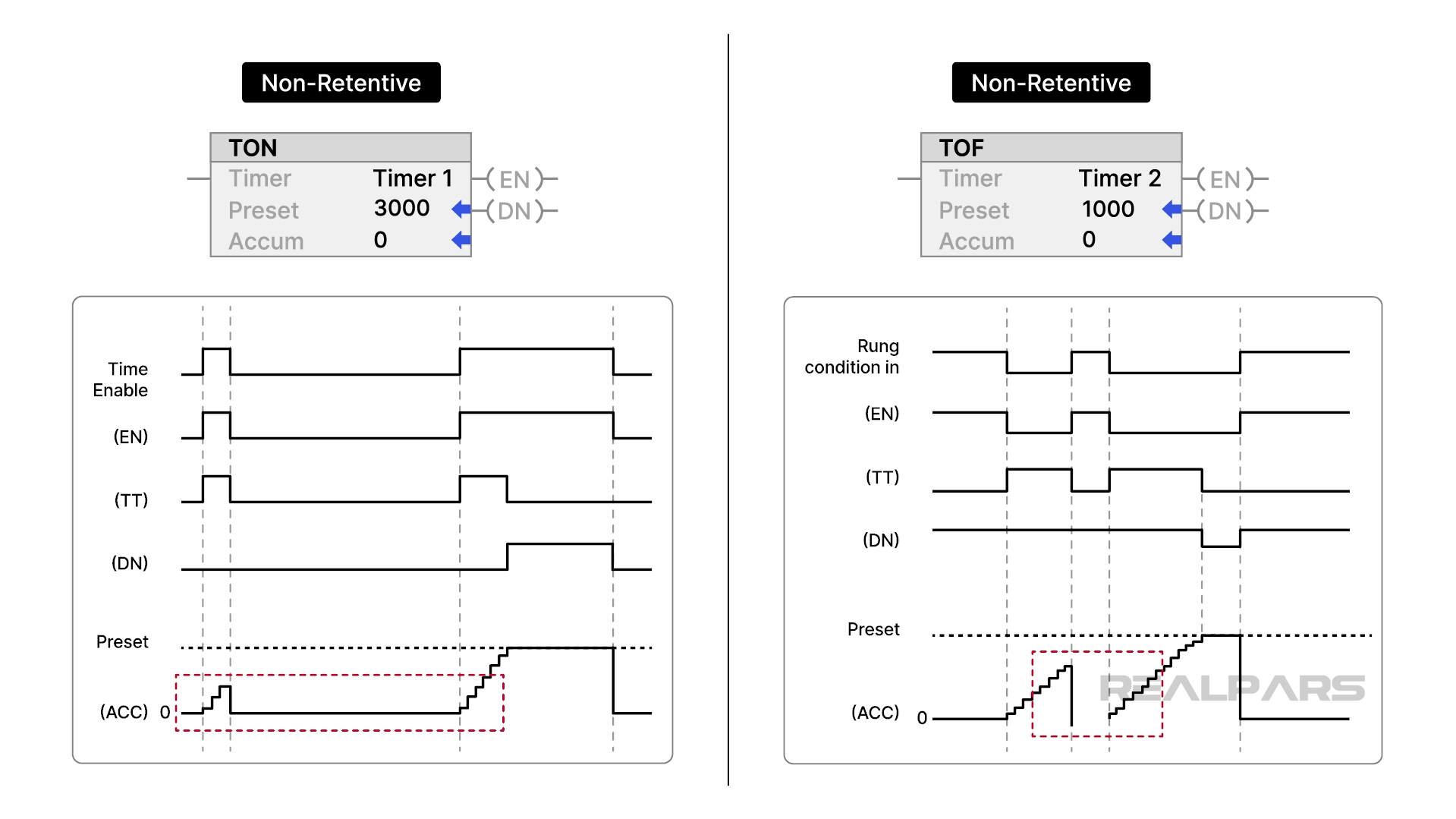
Timer On Delay (TON)
The Timer On Delay, or TON, instruction is used to delay turning on a signal.
When the rung-in condition for the timer is True, the timer is enabled and begins accumulating time. The accumulated time is stored in the ACC member of the timer’s backing tag.
When the accumulated time equals the preset time, the timer is done, and the output, also known as the Done bit, turns on. The preset time is defined by the PLC programmer and is stored in the PRE member of the timer’s backing tag.

When the rung-in condition for the instruction is False, the timer is not enabled. When the timer is not enabled, the accumulated value is reset to 0, and the Done bit is False.
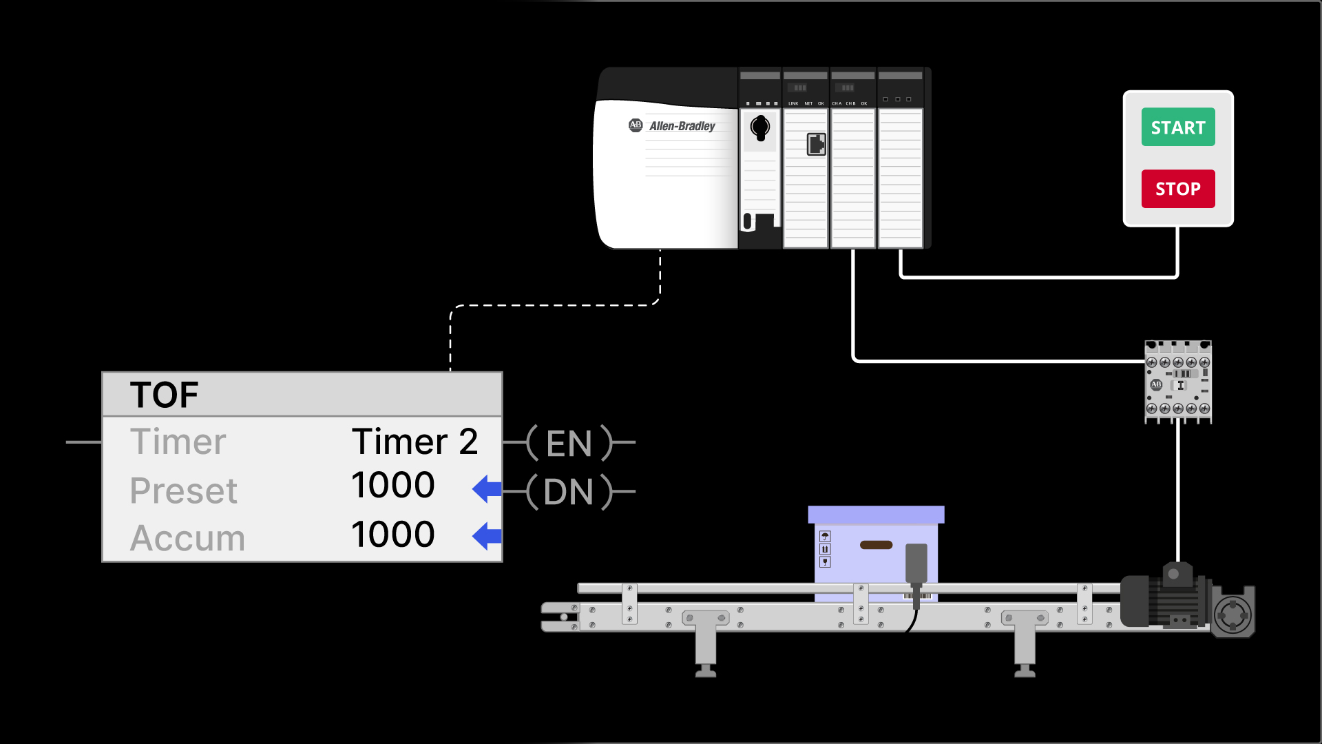
Timer Off Delay (TOF)
The Time Off Delay, or TOF, instruction is used to delay a signal turning off. It is the exact opposite of a TON instruction.

A TOF instruction is enabled when its rung-in condition becomes False.
When enabled, it accumulates time and stores the accumulated time in the ACC member of its backing tag.
When the accumulated time equals the preset time, the Done bit becomes False.

Just like a TON instruction, the accumulated time of the TOF instruction is reset when the timer is not enabled.
Retentive Timer On (RTO)
The TON and the TOF timer instructions are non-retentive instructions. We say that they are non-retentive because they do not retain their accumulated value when the timer is not enabled.
In contrast, the Retentive Timer On, or RTO, instruction is a retentive timer.
The RTO instruction is enabled when the rung-in condition for the timer becomes True. While enabled, the timer accumulates time and stores the accumulated time in the ACC member of its backing tag.
When the timer is not enabled, the accumulated value is retained.
When the timer is re-enabled the accumulated value continues to increment from its last value.
When the accumulated value equals the preset value, the Done bit for the timer is turned on and the accumulated value stops increasing.
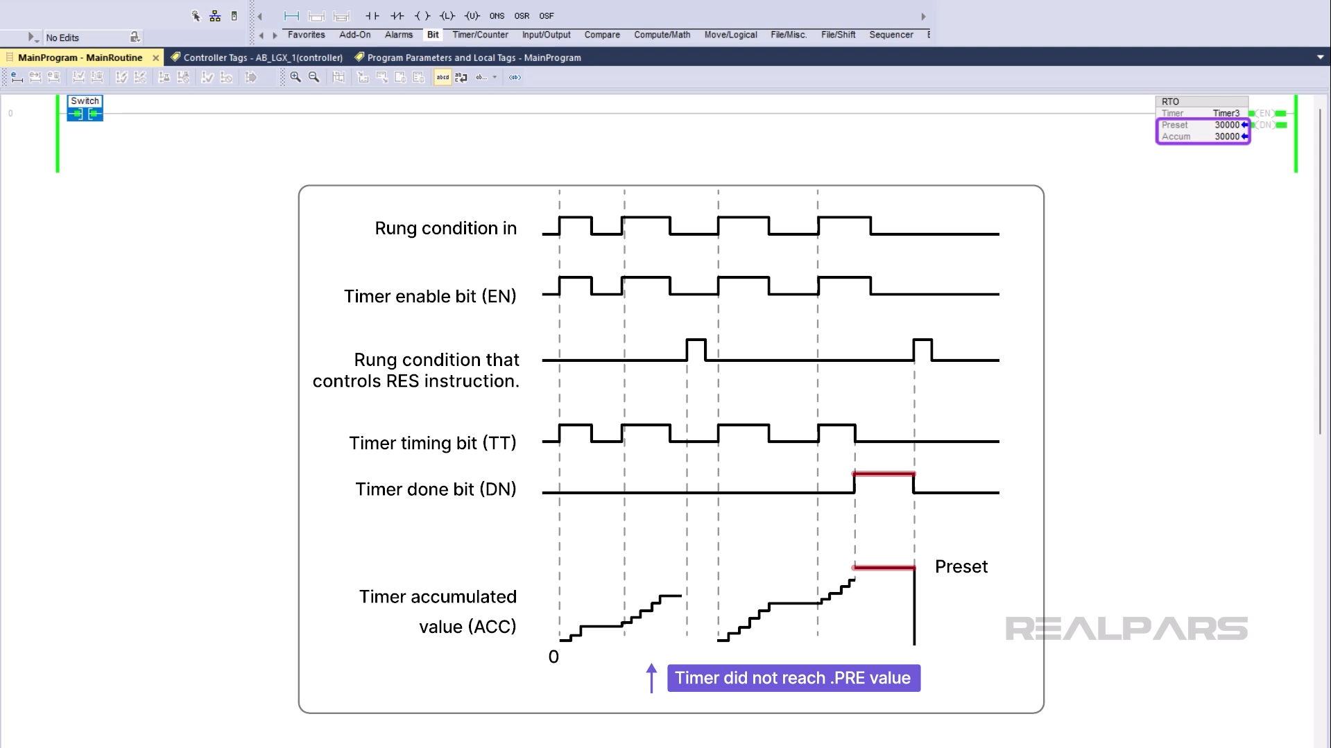
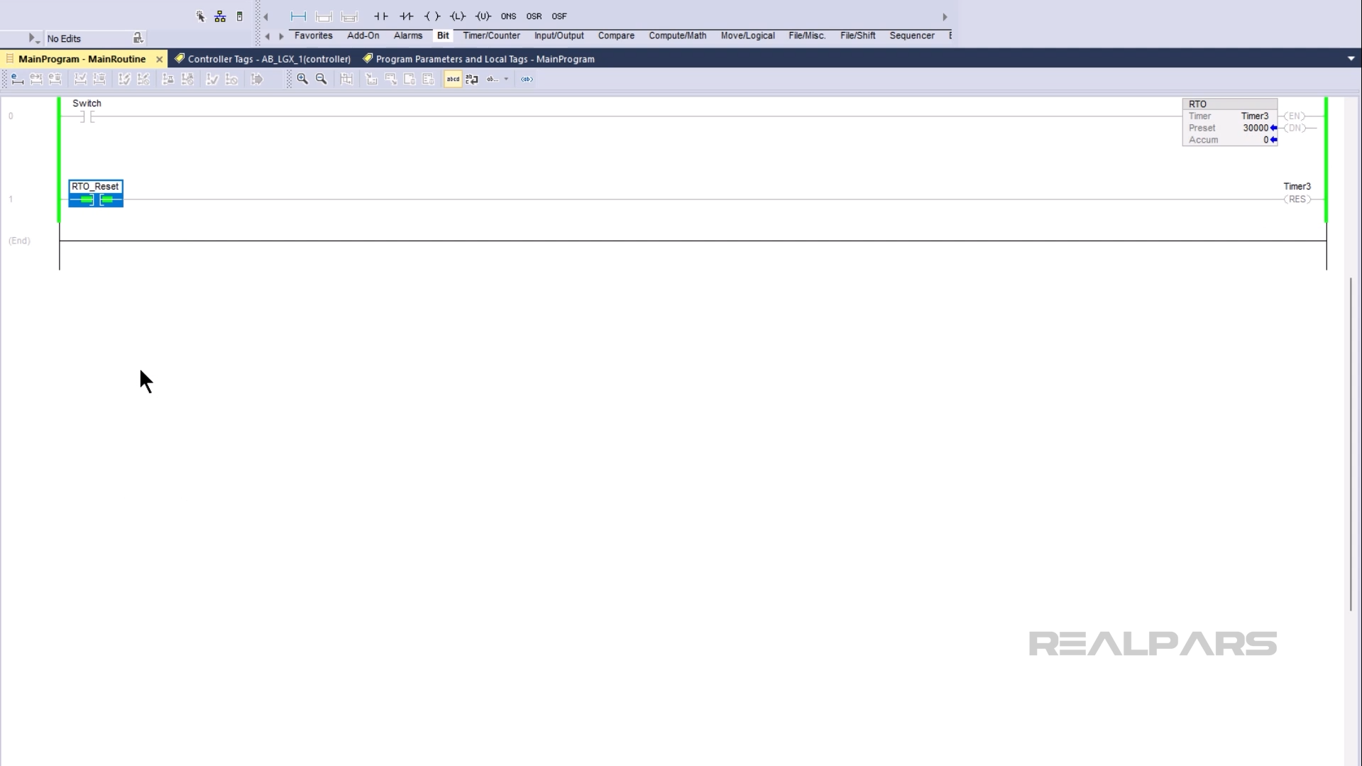
To reset the accumulated value of an RTO instruction, you need to use a Reset, or RES, instruction.
RTO’s are great for tracking total times of events. In Learn Logix 7: Programming with Timers and Counters, we go through an application example of how an RTO can be used to track the total running time of a motor and determine when scheduled maintenance is required.
Wrap-Up
In this article, you learned how timers work in PLC programming in general. You also learned what timer instructions are available for the Ladder Diagram programming language in Studio 5000 Logix Designer and how those instructions work.
It should be noted that there are other timer instructions available in other programming languages like Function Block Diagram in Studio 5000 Logix Designer. These instructions behave slightly differently to the instructions that we have discussed in this article.