
IO-Link is a popular communication technology that is used to connect smart sensors to industrial control systems.
ifm is a founding member of the IO-Link consortium and is a leading manufacturer of innovative IO-Link hardware that is used in many different industries.
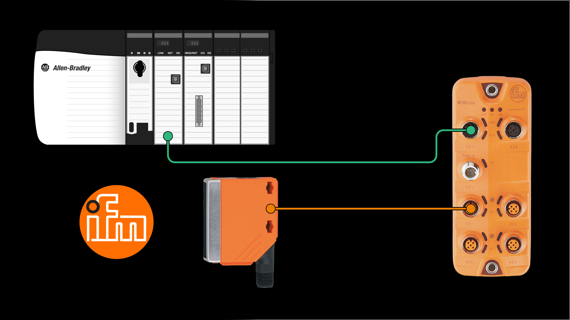
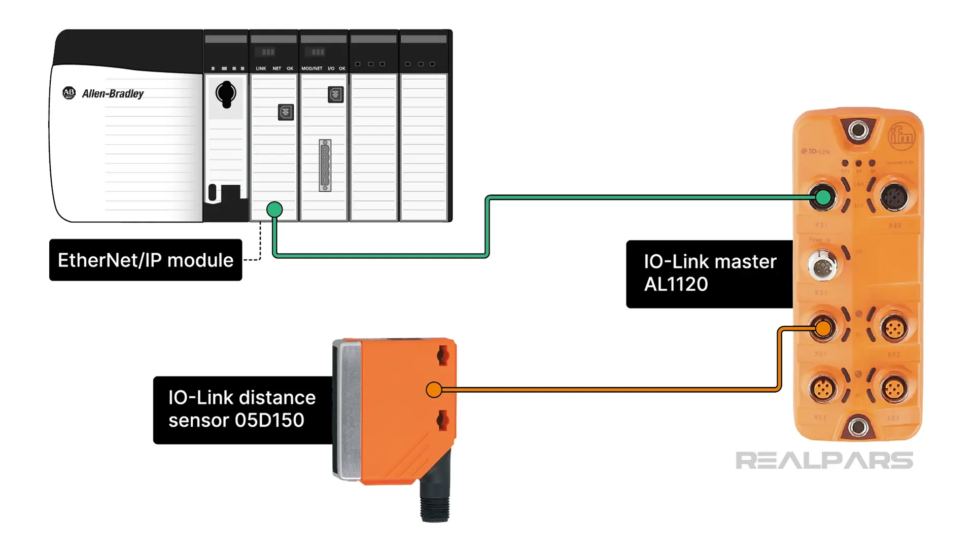
In this article, I’ll show you how to integrate an ifm IO-Link distance sensor into a Logix 5000 control system using an ifm IO-Link master.
Allen-Bradley starter package
ifm provide a Startup Package that contains everything you need to integrate ifm IO-Link devices with Allen Bradley control systems. You can download the Starter Package using the link in the description below.
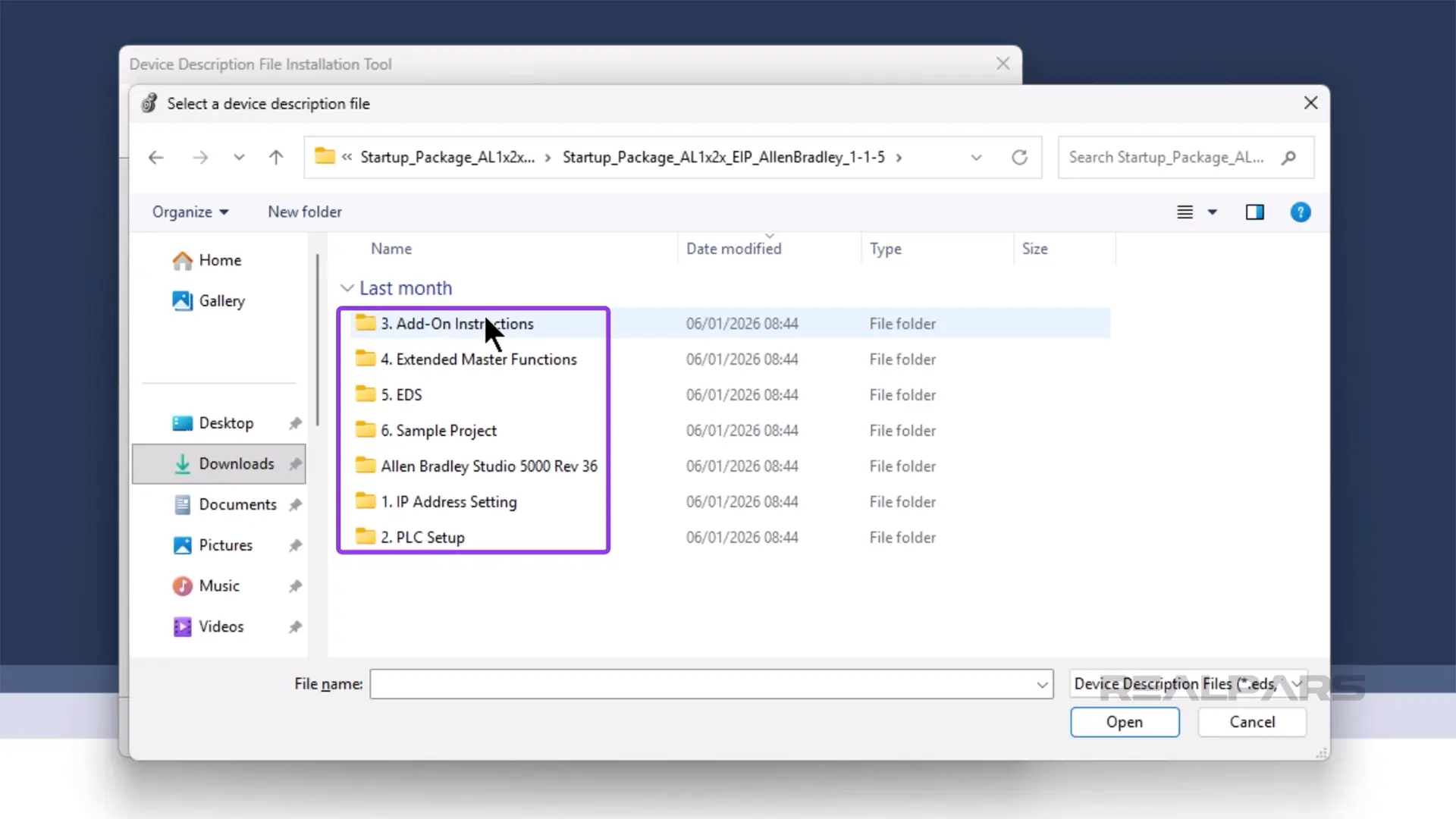
On my computer, I have downloaded and extracted the contents of the starter package. Inside, I can see that it is a set of numbered folders that brings us through the process of integrating ifm IO-Link devices to a control system.
Let’s work through these steps.
Install the EDS files and create the device
In Studio 5000 Logix Designer, I can install the EDS file for the IO-Link master by clicking on Tools and then Device Description Installation Tool.
In the Device Description Installation Tool, I follow the prompts to register a new EDS file.
On the registration page, I browse to folder 5. EDS, which is part of the Startup Package, and select the ifm_IOL_Master_AL1120.eds file, which is the IO-Link master that I am using in this demo, and click Open.
Then I continue the process to register the device.
Now that the device is registered, I can add it to the I/O Configuration of the project. To do that, I right-click on the Ethernet port of the device and select New Module
In the New Module dialog, I search for the AL1120 IO-Link master that I have just registered and click Create to add an instance to the project.
In the New Module dialog, I give the module a name and set the IP address to 192.168.1.250. This is the default IP address of the ifm IO-Link Masters.
Next, I click on Change to open the Module Definition.
In this dialog, I can configure the definition of the IO-Link master. In the name column, I verify that Exclusive Owner IO-Acyc-Diag is selected.
Then I change the size units from SINT to INT and verify that the size is correct. For a 4-port IO-Link master, which is what I’m using in this example, the input size should be 123, and the output size should be 87. For an 8-port IO-Link master, the input size should be 223, and the output size should be 151.
Now that the module is configured, I click OK to close the Module Definition dialog and select Yes in the warning dialog.
Then I click OK to close the New Module dialog, and finally, I click Close to close the Select Module Type dialog.
Now we are ready to write the logic to retrieve data from the distance sensor.
RealPars for Business
Train your team and reduce downtime
Program the PLC
The easiest way to communicate with an ifm IO-Link device is to use the Add-On instructions that have been developed by ifm.
To do that, I expand the Assets folder of the project, right-click on the Add-On Instruction folder, and select Import Add-On Instruction.
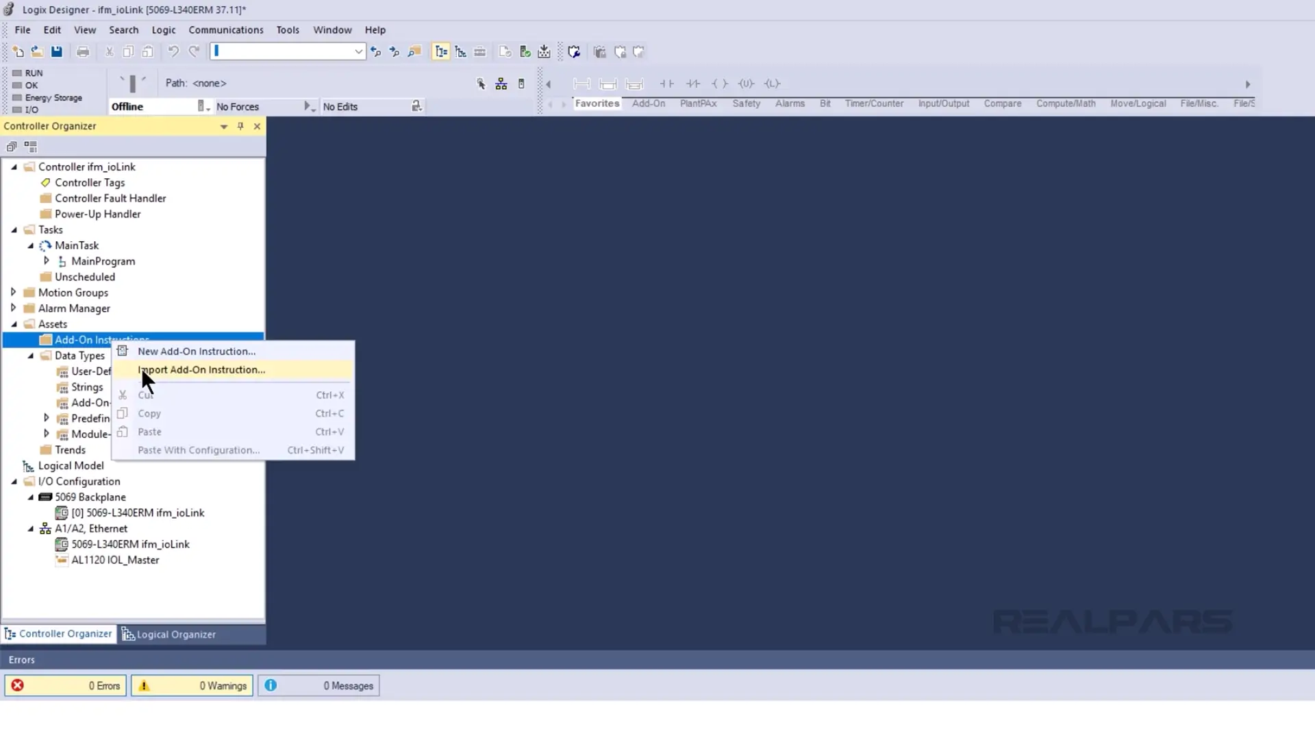
In the Import Add-On Instruction dialog that opens, I browse to the folder 3. Add-On Instructions, which is part of the Startup Package.
In this folder, I select 1. ifm devices and browse to the O5D_OIDxxx folder. This folder contains the Add-On Instructions for the O5D150 distance sensor that I am using in this demo.
In this folder, I select the 4 port Add-On Instruction since my IO-Link Master has 4 ports and click Open to import the Add-On Instruction.
On the Import Configuration dialog, I click OK to finalize the import and the Add-On Instruction is now available in the Assets folder of the project.

To use this Add-On Instruction, I open the MainRoutine and drag the Add-On Instruction from the Assets folder and drop it on the rung.
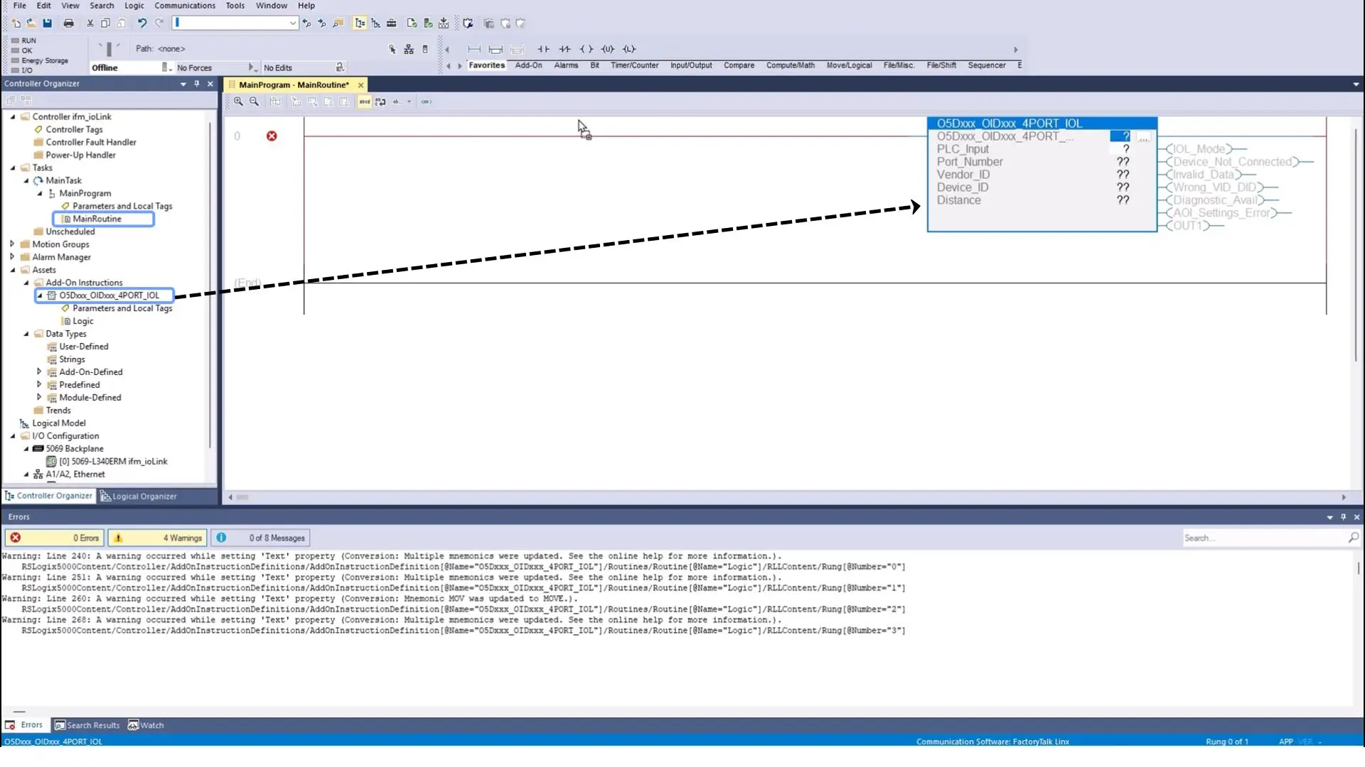
Next, I create a backing tag for the instruction by right-clicking the question mark and selecting New Tag.
In the New Tag dialog, I give the tag a name and click Create.
Now, I can parameterize the instruction by adding a reference to the PLC Input area and configuring the Port Number as shown here. In this case, the sensor is connected to the first port of my IO-Link master so I set the Port Number to 1.
Now we are ready to download and test the project
Test the project
In Studio 5000 Logix Designer, I click the RS Who button to open the Who Active dialog.
In this dialog, I select the controller that I want to download to and click Download.
In the Download dialog, I click Download to confirm that I want to download to the PLC.
When the download is complete, I click Yes to put the controller back into Remote Run mode.
In the I/O Configuration, I can see that the PLC is able to communicate with the IO-Link master without errors.
And in the MainRoutine, I can see data coming in from my sensor.
Wrap-Up
In this video, you saw how you can integrate ifm IO-Link hardware into an Allen-Bradley control system.
Request Custom Training
Online or on-site. Built around your company’s equipment, skill gaps, and project needs.
https://www.realpars.com/custom-training