
.jpg)
Ladder Logic is one of the five PLC programming languages in the IEC 61131-3 Standard. If you’re starting to tune out, stick around a bit longer. Maybe we’ll convince you to keep watching. You won’t hear anything more about IEC 61131-3.
By the end of the article, you'll be able to read a standard industrial program and understand exactly how the machine thinks.
Prefer watching instead? Check out the video below, or keep reading for the full step-by-step explanation.
Electrical schematic
Ladder logic was the first PLC language developed and remains the most widely used today. We don’t want to bore you with historical reminiscing, but ladder logic was designed to resemble the electrical schematic diagrams of hard-wired relay logic.
This made it very popular among non-programmers, such as electricians and other maintenance personnel.
Ladder Logic isn't just about looking like an electrical schematic; it’s about understanding system operation and real-time troubleshooting. In a factory, seeing rung instructions go True or False is much faster than debugging lines of code.
Alright, let’s get to it. This electrical schematic is a classic Motor Start/Stop configuration.
The Stop Switch, Start switch and Control Relay are hardwired together to operate a Motor. Historically, for ease of understanding and standardization, this type of electrical circuit was drawn to look like a ladder. And has remained so today.
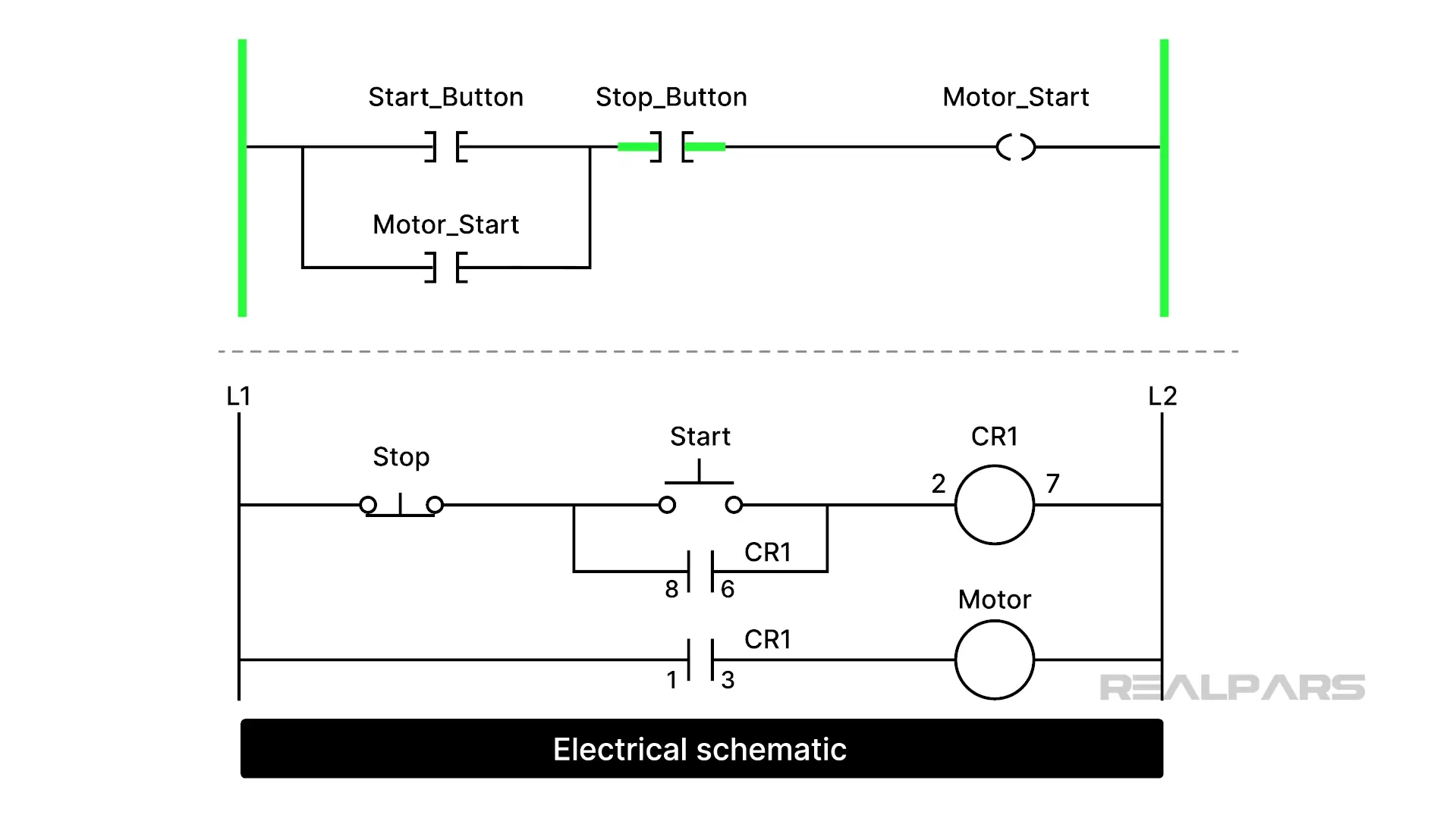
How does it work? Pushing the Start button energized CR1. Contacts 8 and 6 close and keep CR1energized after the Start button is released.
Contacts 1 and 3 close, and the Motor starts. Pushing the Stop switch breaks the CR1 energizing path, and the motor stops.
Looking at a different schematic version of the same electrical circuit, the relay ladder version is the clear winner for interpreting circuit action.
Ok, let’s forget about that ugly second schematic and focus on the relay ladder version.
We said earlier that the Stop Switch, Start Switch, and Control Relay were hardwired together to operate a Motor.
Making changes or replacing defective components often required cutting wires or, at the very least, removing them from terminals and rewiring the entire system.
PLCs came along and made things so much easier. We got rid of all of the hardwiring and many of the components.
How Ladder Logic works
Let’s look at how PLCs and Ladder Logic perform the motor Stop/Start action.
We still need the Stop and Start Buttons, but say goodbye to the Control Relay CR1.
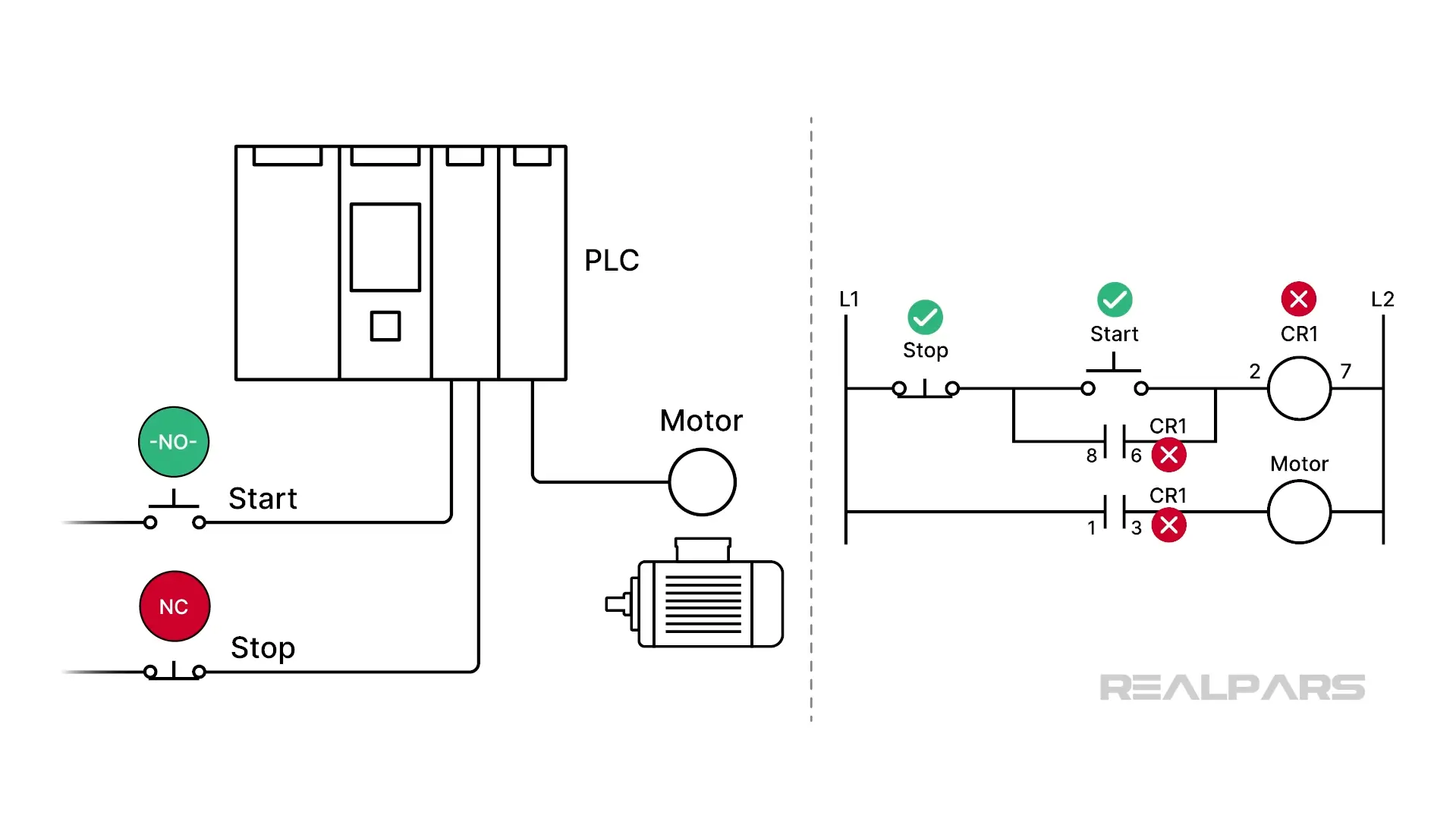
The Stop and Start switches are no longer wired together. Each switch is connected to a separate input on the PLC. This is oversimplified, but you probably get the picture.
The motor is connected to an output of the PLC. This is another simplification, as PLCs don’t usually operate motors directly. But this will work for our explanation.
OK, so this is where the ladder logic program comes into play. The purpose of the ladder logic is to determine the motor's status based on the switches' status. In other words, the program examines the switch conditions and then decides what to do with the motor.
How does that happen?
Basic PLC instructions
Every vendor PLC ladder-logic programming language uses symbols to represent instructions. Thankfully, the graphic symbols for these instructions are almost identical. Unfortunately, the names are not.
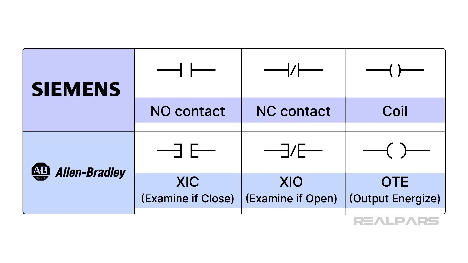
Let’s have a look at the three most commonly used instructions in any PLC ladder logic program.
We’ve got two input instructions and one output instruction.
The first input instruction resembles a normally open relay contact. That’s exactly how it operates in ladder logic.
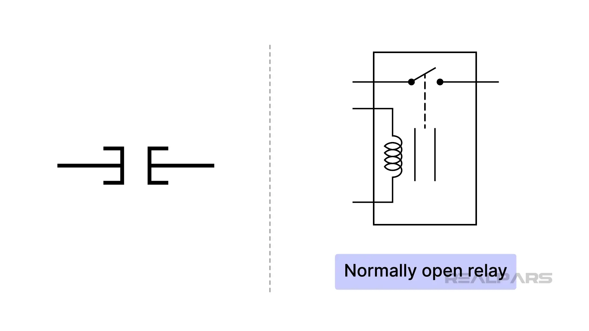
Siemens calls it an NO contact, while Allen-Bradley calls it an XIC, or Examine if Close Contact.
The second input instruction resembles a normally closed relay contact. That’s exactly how it operates in ladder logic.
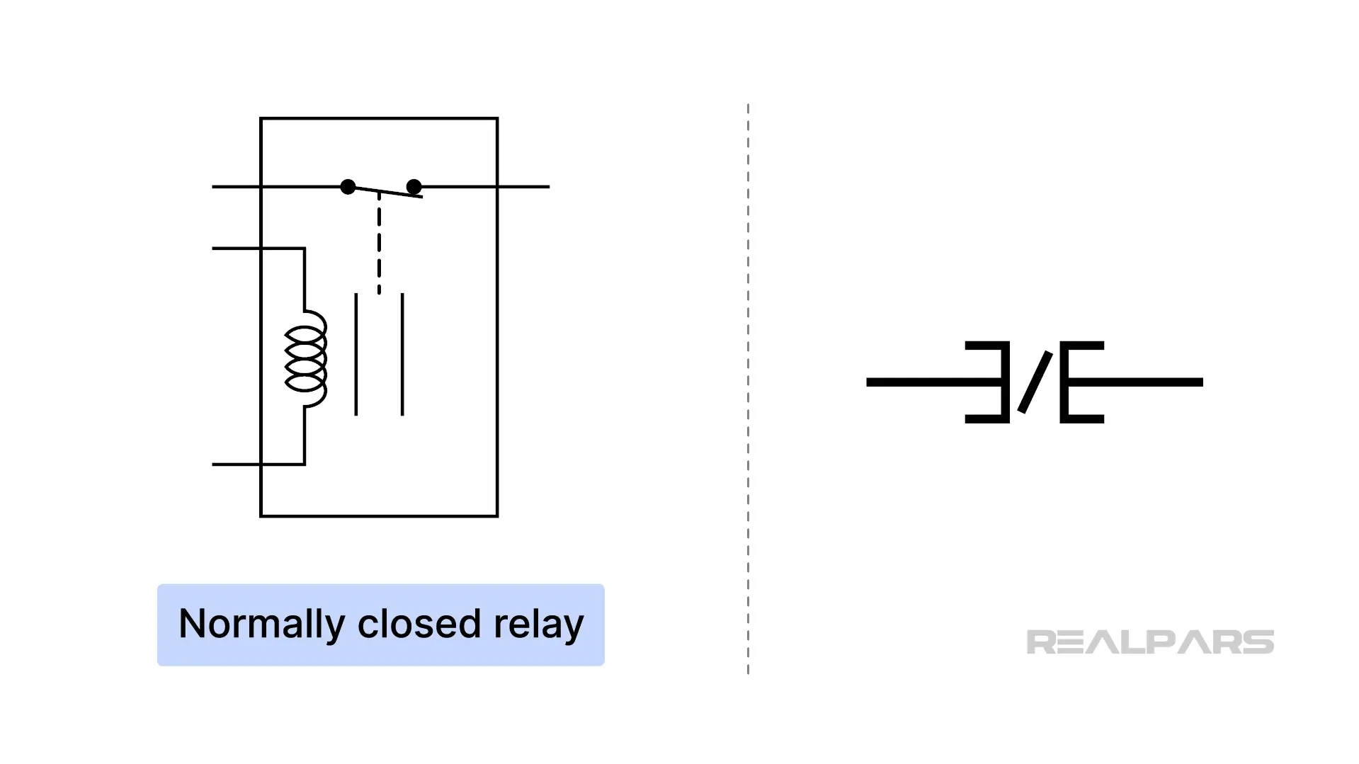
Siemens calls it an NC contact, while Allen-Bradley calls it an XIO, or Examine if Open Contact.
Here’s a tip for you to remember. They are graphical instructions displayed on a screen, not physical components. They don't 'click' shut or 'pop' open like real contacts.
For both of these instructions, closed is TRUE and open is FALSE.
For Allen-Bradley, a small GREEN bar indicates TRUE.
The output instruction resembles a coil
Phoenix Contact calls it a coil, while Allen-Bradley calls it an OTE, or Output Energize.
Ok, so now we’ve investigated the three most common instructions. So what do we do with them?
Well, we put them into a ladder-logic program and connect them. Keep in mind that these instructions are graphical representations of computer code.
Let’s look at a typical ladder logic program.
Think of the vertical lines on the left and right as Power Rails.
Rungs are connected to each end of the power rails and populated with instructions.
Input instructions are connected to the left-hand power rail, and output instructions to the right.
The left rail is the source of Logical Power. For an output on the right to turn on, you have to create a continuous path of 'True' instructions to get the logical power from the left rail to the right.
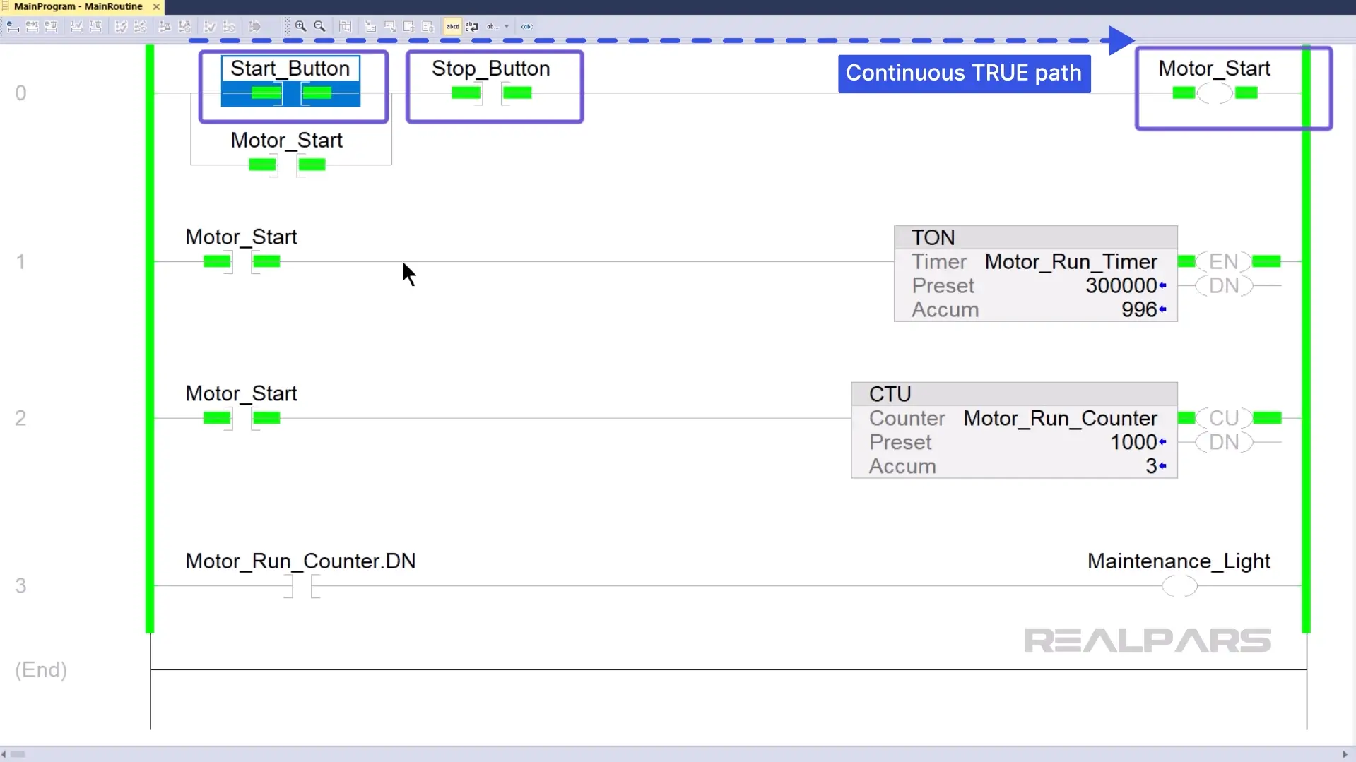
Let’s figure out how the first run behaves.
The Motor_Start output will turn on when the Start_Button and Stop_Button instructions create a continuous path of 'True' instructions.
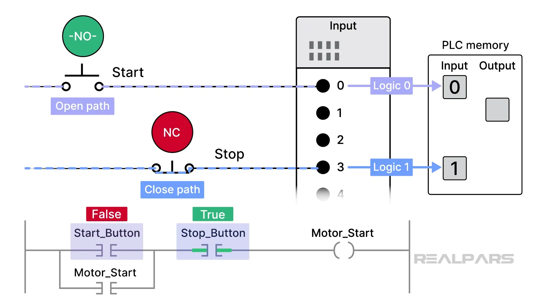
Why is the Start_Button instruction False and the Stop_Button instruction True?
These input instructions receive their marching orders from the physical devices connected to the PLC.
How does that happen? Inside the program, the Start_Button instruction is configured to monitor the status of terminal 0 on the PLC input, and the Stop_Button instruction is configured to monitor the status of terminal 3.
An open path to the terminals results in a logic “0”, and a closed path results in a logic “1” . These logic values are stored in specific PLC memory locations.
A logic “0” tells an associated instruction to remain in its present state.
A logic “1” tells an associated instruction to change to its opposite state.
So, without pushing any physical buttons:
- Terminal 0 will produce a logic”0”, the Start_Button instruction remains in its present FALSE state.
- Terminal 3 will produce a logic”1”, the Stop_Button instruction changes to its opposite state, TRUE.
Phew……let that sink in for a minute or two. Watch the last few minutes again if you are still a bit fuzzy.
When the Motor_Start output goes TRUE, a logic “1” is placed in a specific memory location, causing the PLC to run the motor.
What needs to happen to get the motor to run?
Pressing the Start switch sets the Start_Button instruction to TRUE, creating a continuous path of TRUE instructions to the Motor_start output instruction.
The Motor_Start input instruction also goes TRUE, providing a path around the Start_Button instruction? Why? This will ensure that the motor continues to run even after the Start switch is released.
Pressing the Stop switch sets the Stop_Button instruction to FALSE, breaking the continuous path of TRUE instructions; the Motor_Start instruction goes FALSE, and the Motor stops.
Alright…..we’ve covered the operation of the three basic instructions and seen how they function in a simple ladder logic rung.
Analyzing overhead door Ladder Logic
Let’s have a look at another ladder logic program and see if we can determine what it does.
Based on what we’ve talked about in this article, let’s analyze the ladder logic for an overhead door.
The control console has three pushbuttons and three indicator lamps.
The Door_Shut output instruction is TRUE; therefore, the SHUT light should be on, and it is.
The Door_Ajar output instruction is FALSE; therefore, the AJAR light should be off, and it is.
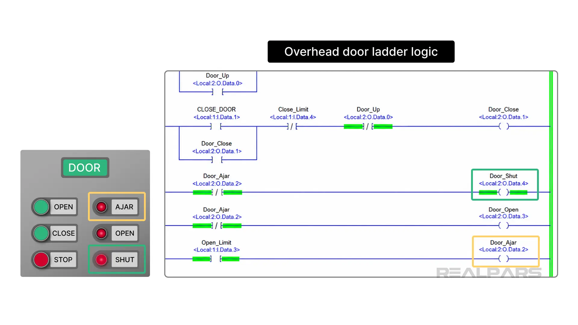
Here’s a tough question to contemplate. What type of switch is the STOP switch? Is it Normally-open or normally-closed?
The STOP instruction is an XIO, or normally-closed, and it is currently TRUE as indicated by the Green bar. So, there must be a logic “0” stored in its allocated PLC memory location. That means that the actual STOP switch must be a normally-open type.
Wrap-Up
Wow…that was fun…….
We hope you enjoyed following along.
And just like that, you’ve gone from staring at a drawing that made no sense to deconstructing an overhead door system.
Whether you’re looking at a Siemens NO contact, an Allen-Bradley XIC, or a Phoenix Contact coil, the logic is the same: sort through the TRUE and FALSE instructions and you’ll find the answer.