
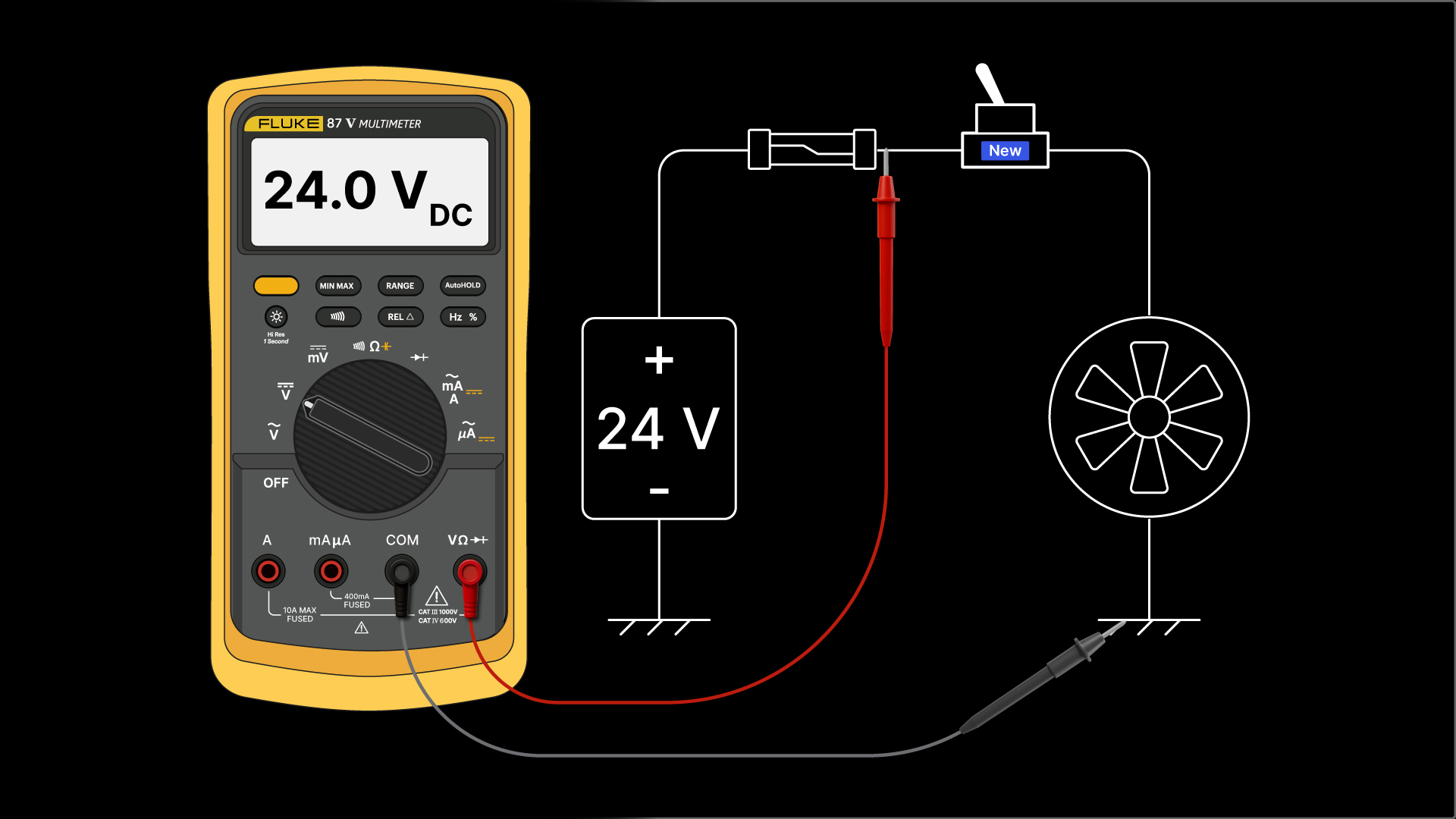
Troubleshooting. The word strikes fear into many, but for seasoned service engineers, it’s just another day in the office.
Imagine you've just arrived at a plant. You are the field engineer tasked with bringing a downed system back to life so production can restart.
Here’s a keeper for you. The best troubleshooter isn’t the one who fixes the fault after replacing a bunch of parts. It’s the one who replaces the right part the first time and understands why it failed.
In this article, I’ll talk about what effective troubleshooting really means and how to get started. You’ll learn, or perhaps be reminded, that understanding a handful of fundamental electrical principles will make you a faster, more confident troubleshooter.
Alright…let’s get back to the plant and our troubleshooting adventure.
Where do you begin? Not by frantically swapping parts or by taking a bunch of multimeter measurements just because you are anxious to do something.
You ask yourself two simple questions:
- What are the symptoms?
- What is the system doing, or what isn't it doing?
Quite often, it’s the control room or station operators who can help you out here.
They can also tell you what happened right before the system went down.
This may be obvious, but it’s worth stating. You can’t fix it if you don’t know how it works; you're lost at sea if you don't know what normal looks like, and you’ll just be guessing.
After searching for visible signs of damage, such as broken or burnt components, it's time to open the toolbox.
Ok, let’s move on to the electrical principles mentioned earlier.
Principle 1: Current changes because resistance changes
Current may have changed due to a change in the supply voltage, but that’s less likely, since the voltage is usually fixed. With that in mind, according to Ohm's Law, current increases when resistance decreases and decreases when resistance increases.
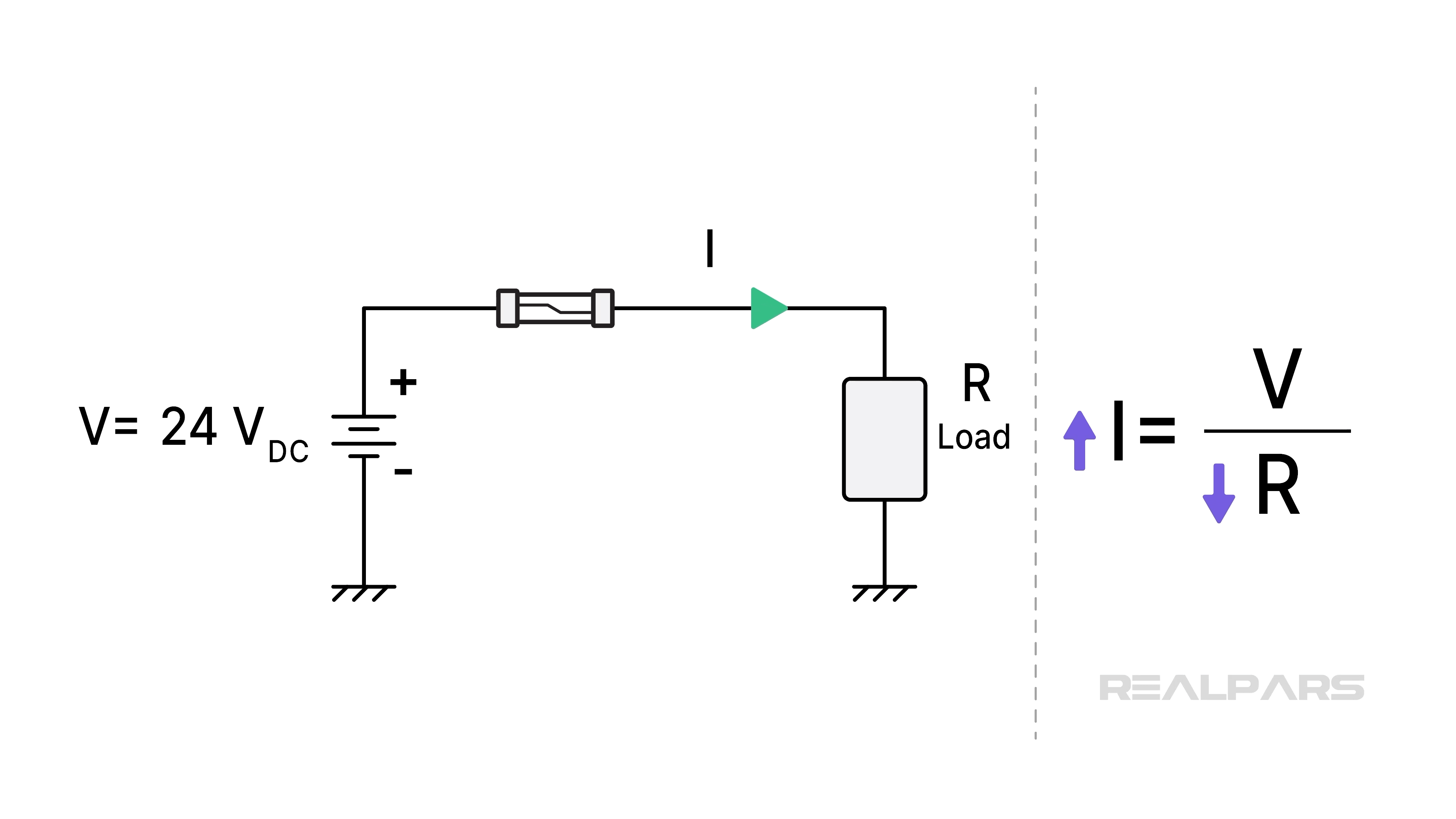
You need to determine the cause of the change in resistance. Is it a radical change, like a short circuit that blows a fuse? Or an increase in resistance due to a partially broken conductor or a corroded connection?
If you suspect a short circuit, it’s easy to put in a new fuse, but don’t do it. A better approach is to determine what caused it to blow.
Principle 2: Unexpected voltage drop indicates high resistance
Let’s break that down.
You shouldn’t measure any significant voltage across a closed switch or a good fuse. Why? Because each has a normal resistance near zero ohms.
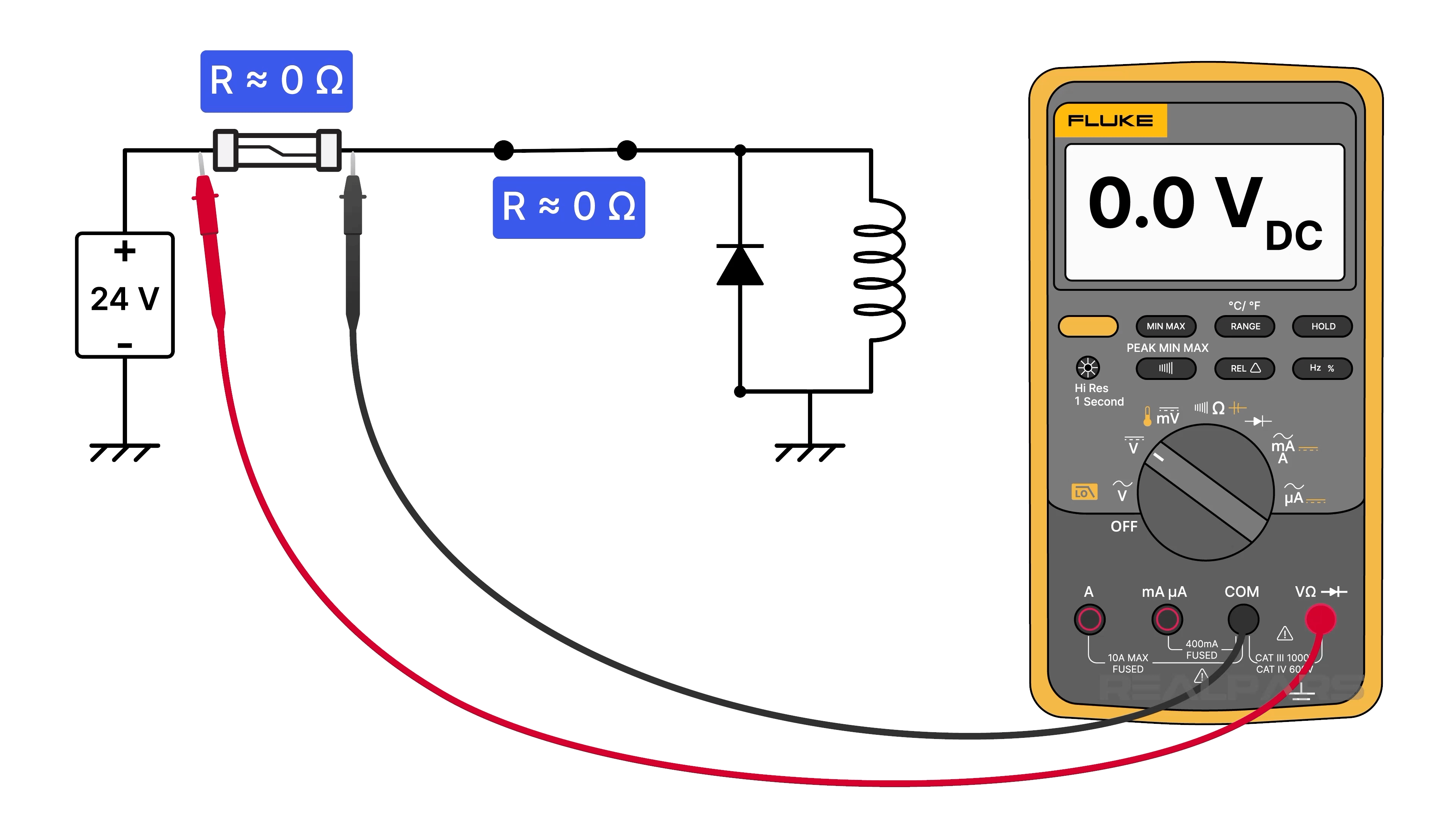
If you do measure voltage across a closed switch, it has an unwanted increase in resistance.
If you have a decrease in voltage across a solenoid or any other load, it means there is a voltage drop increase across something else.
Good wires and terminals have virtually zero resistance, so there is no voltage drop across them. But if either has an increase in resistance, you no longer have a zero-volt drop across them.
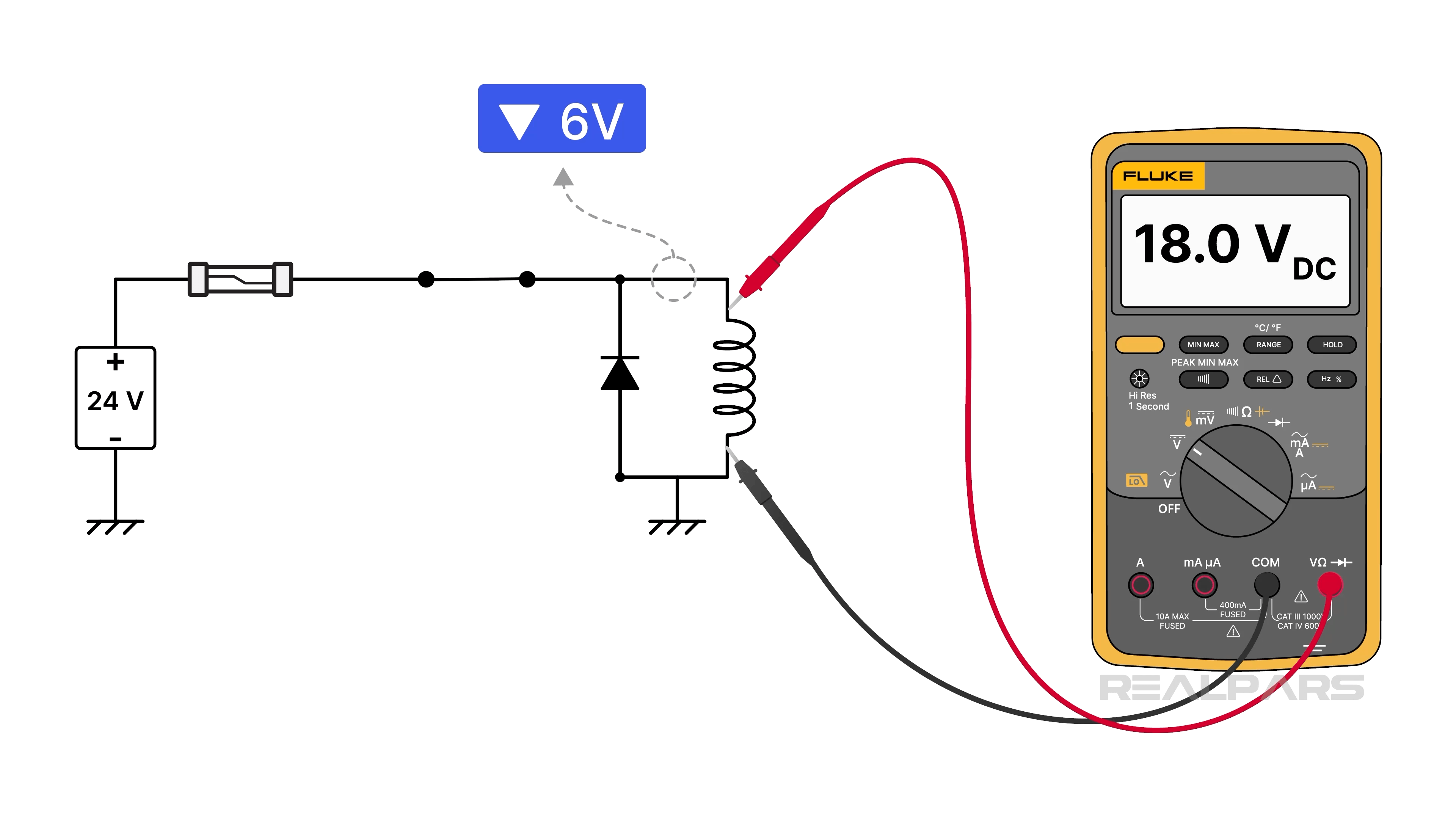
So, if you have a solenoid that chatters, you may find a lower-than-normal voltage across it due to a voltage drop across a corroded terminal.
Principle 3: Open circuits stop current, but not voltage
That may sound like an odd statement, given that voltage doesn’t move and current is a measure of electron flow.
To clarify, an open circuit, such as a broken wire or an open switch, stops electron flow, and a source voltage will appear across it. According to Ohm’s Law, there will be no other voltage drop anywhere else in the circuit because there’s no current flow.
If you place your meter leads across a good closed switch in a 24VDC circuit, you will read 0 VDC. If you read 24 VDC, the switch is open. If it's supposed to be closed, you’ve got a bad switch.
Similarly, if you measure 24 volts across a fuse, it goes into the garbage.
Why is there a 24-volt drop across an open circuit? This can be explained using Kirchhoff’s voltage law, which states that the sum of the voltages around a closed loop is zero. As soon as you connect your multimeter to the circuit, you’ve closed the loop.
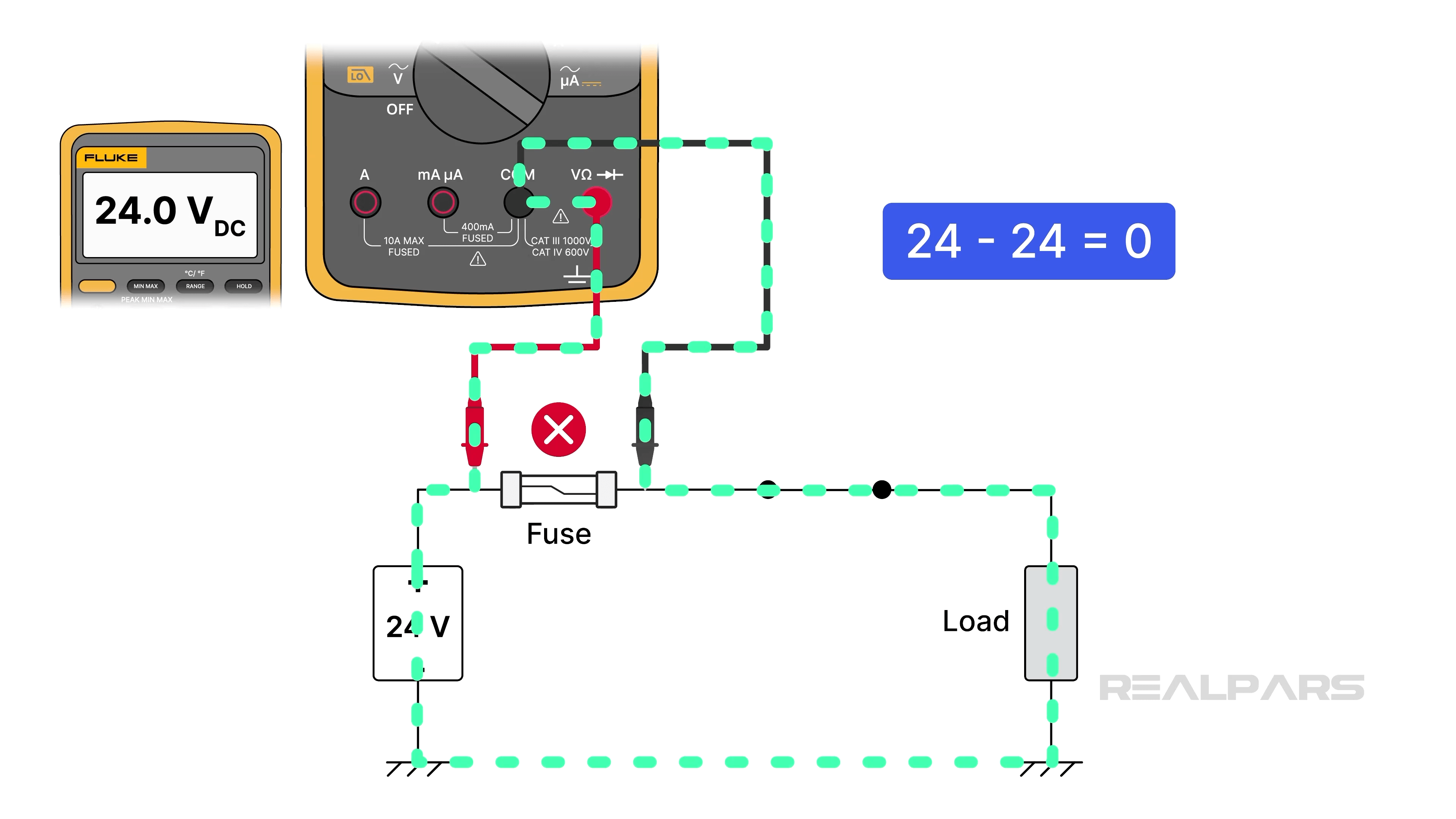
Measuring voltages across every component works, but it isn't very efficient and often confusing. I’ll get to a more efficient troubleshooting method shortly.
Principle 4: Voltage measurements are usually better than resistance measurements
While live-testing voltage measurements are easier to perform and often eliminate the need for resistance measurements, they must only be performed under safe, controlled conditions.
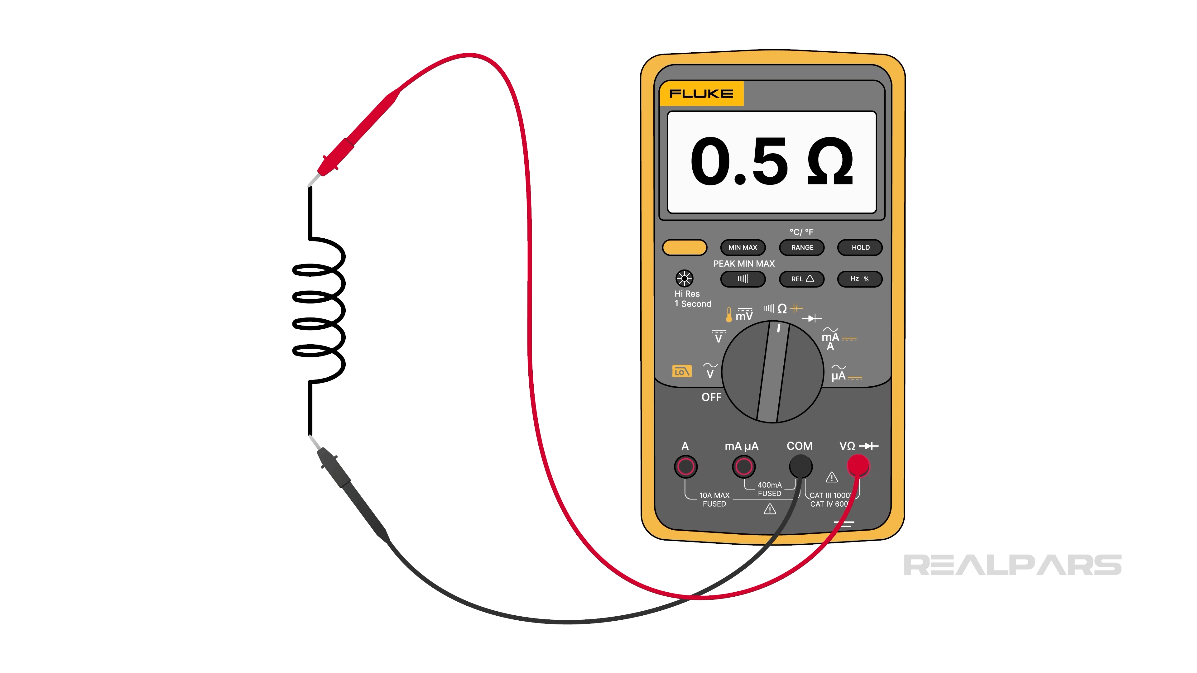
Voltage measurements do not require disturbing the circuit under test. Components need not be removed, and wires need not be cut. For resistance measurements, the component must be completely isolated, providing the only current path between the two multimeter leads.
Consider a voltmeter connected directly across a fuse that indicates 24 volts. The fuse is blown. Would you bother to remove the fuse and test it with an ohmmeter? Of course not.
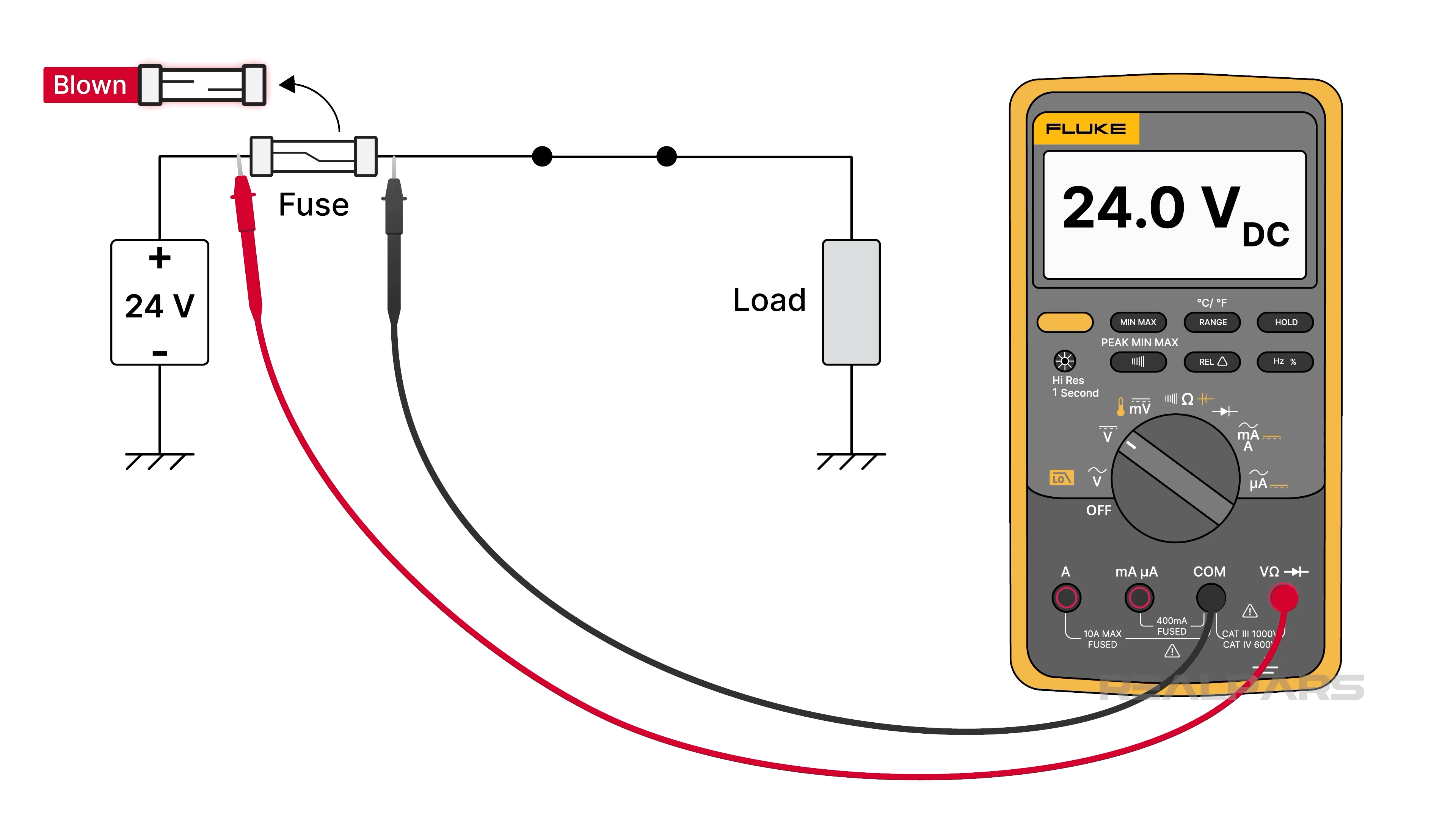
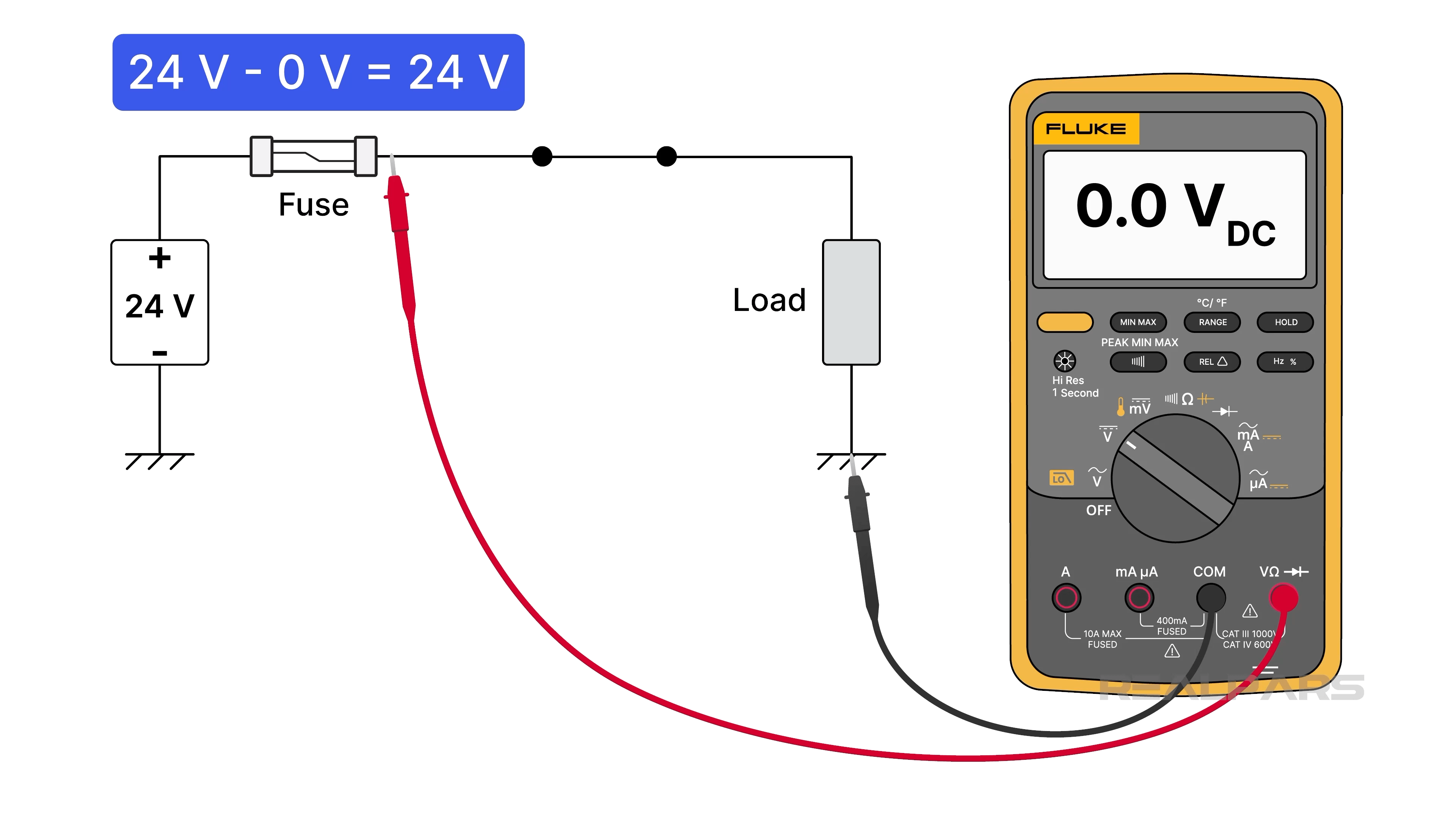
Instead of measuring across components using both hands, seasoned troubleshooters secure the voltmeter's black lead to common and use the red lead to probe selected points.
Let’s test the same fuse. The voltage from the fuse line side to common is 24 volts, and 0 volts to common on the load side. If you subtract the 2 measured voltages, you’ve mathematically derived the 24-volt drop across the fuse.
Just to be clear, voltage measurement isn’t a one-size-fits-all approach. For example, sometimes you have no alternative but to use your ohmmeter because a voltmeter measurement is not possible.
For example, if one solenoid is shorted in a 2-solenoid parallel configuration, no voltage measurements will help to identify the defective solenoid. Why not? Because the fuse will be blown, opening the circuit.
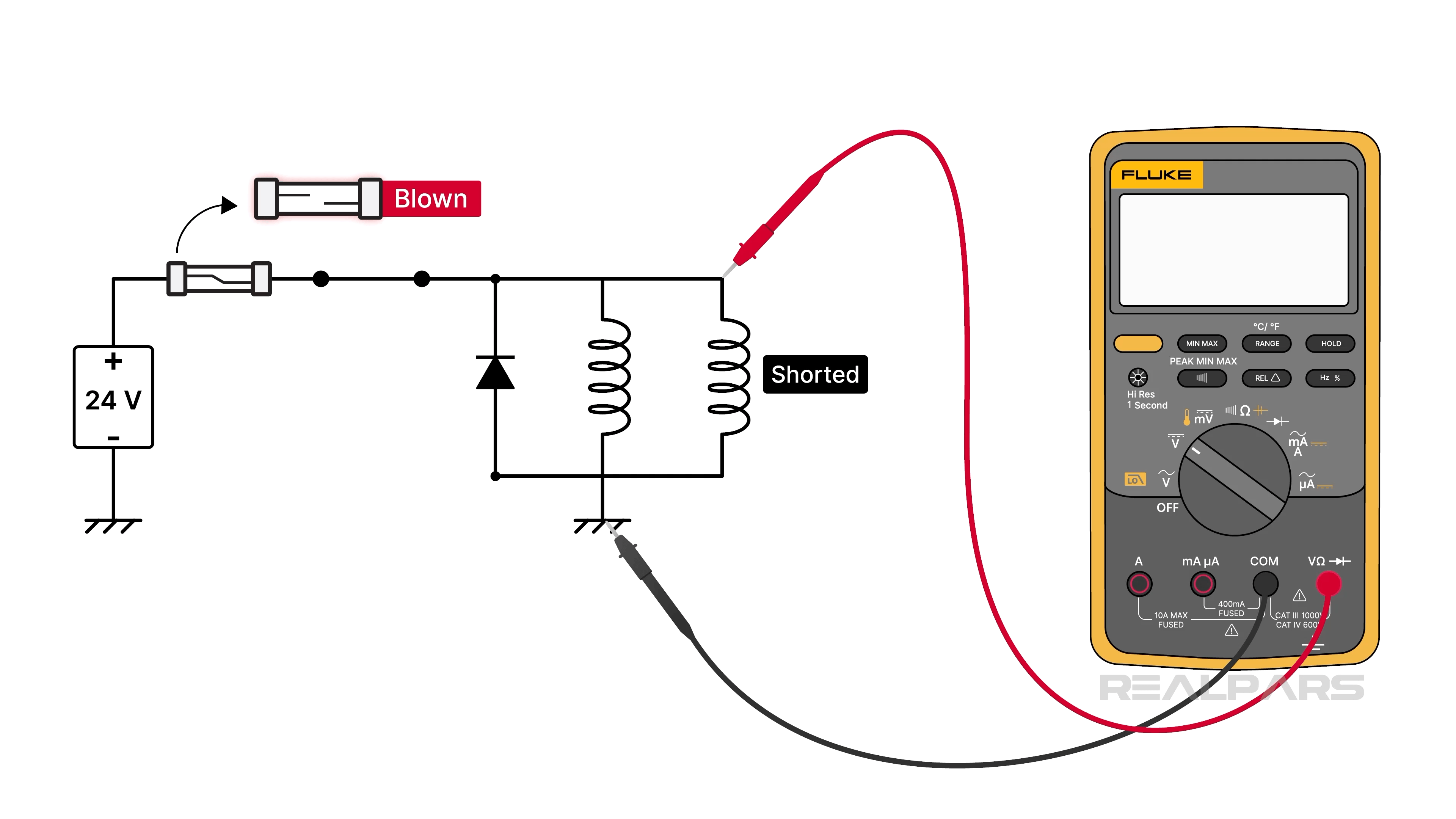
The solenoids must be tested individually using an ohmmeter.
Principle 5: Divide and conquer – use the half-split method
Experienced troubleshooters don't check every component. They don’t start at the beginning or the end. Why not start in the middle and eliminate half the circuit right away? If you continue with half-splitting, your troubleshooting time will be considerably reduced.
The purpose of each measurement is to hopefully point you in the right direction.
Principle 6: Every measurement should confirm a theory
Notice I said hopefully… A critical error made by many troubleshooters is taking a measurement without an expectation of the result.
You shouldn’t take a measurement if you have no idea what the measurement means. Every measurement should take you in a new direction. Don't measure because you can. Measure because you're trying to confirm something.
Principle 7: Verify before replacing
Victory! You think you found the faulty culprit. Not so fast. Always verify the surrounding wiring before replacing the suspected bad component unless it’s blatantly obvious.
Take a few minutes to check for loose screw terminals, broken ferrules, corroded connectors, and damaged cables. You might fix the problem by tightening the wire during reassembly.
Prove the component itself is rightfully destined for the garbage before you replace it with a new one.
Principle 8: Why did it fail?
Everything is working again, but now it’s time to look for the root of the problem. What caused the failure? Are you going to be replacing the same component again in a few weeks or a month from now? If you don't ask why, you aren’t closing the book on this troubleshooting adventure.
Troubleshooting is a learned skill. Seasoned troubleshooters don’t rely on the roll of the dice; they rely on electrical principles they’ve proven over the years. Methodical thinking, forming logical sequences, and minimal optimized measurements always lead to success.
Conclusion
Back to that plant floor. The system is down, the operators are waiting, and every minute costs money. You now have a plan. Ask what the system is doing and what it is not. Know what normal looks like. Take every measurement to prove a theory, not out of habit. And when it runs again, ask why it failed. Anyone can swap parts until something works. A skilled troubleshooter gets it right the first time, and walks away knowing what caused the fault. Try the half-split method on your next call and see how much time you save.
Want to go deeper? Our Industrial Electrical Maintenance courses cover fault finding, test equipment, and real industrial systems. And if your team needs the same skills, RealPars Custom Training is built around your equipment.

