
The two most common electrical faults are open and short circuits. The most commonly misused fault description is a short circuit, as in ... hmmmm it’s not working, so there must be a short somewhere….
As Control Engineers, Technicians, and Electricians, we all studied electrical theory and can Thevenize any paper circuit thrown at us. But most of us didn’t receive a solid foundation in troubleshooting skills, or were shown how to properly isolate a fault with a DMM (Digital Multimeter).
In this article, we’ll show you how open and short circuits differ electrically and how each can be diagnosed and isolated during systematic multimeter testing.
Open circuit
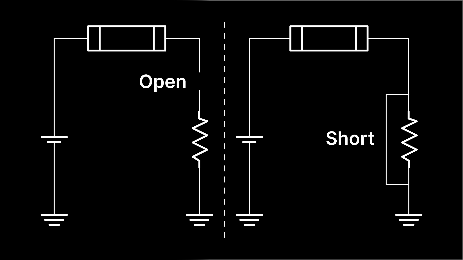
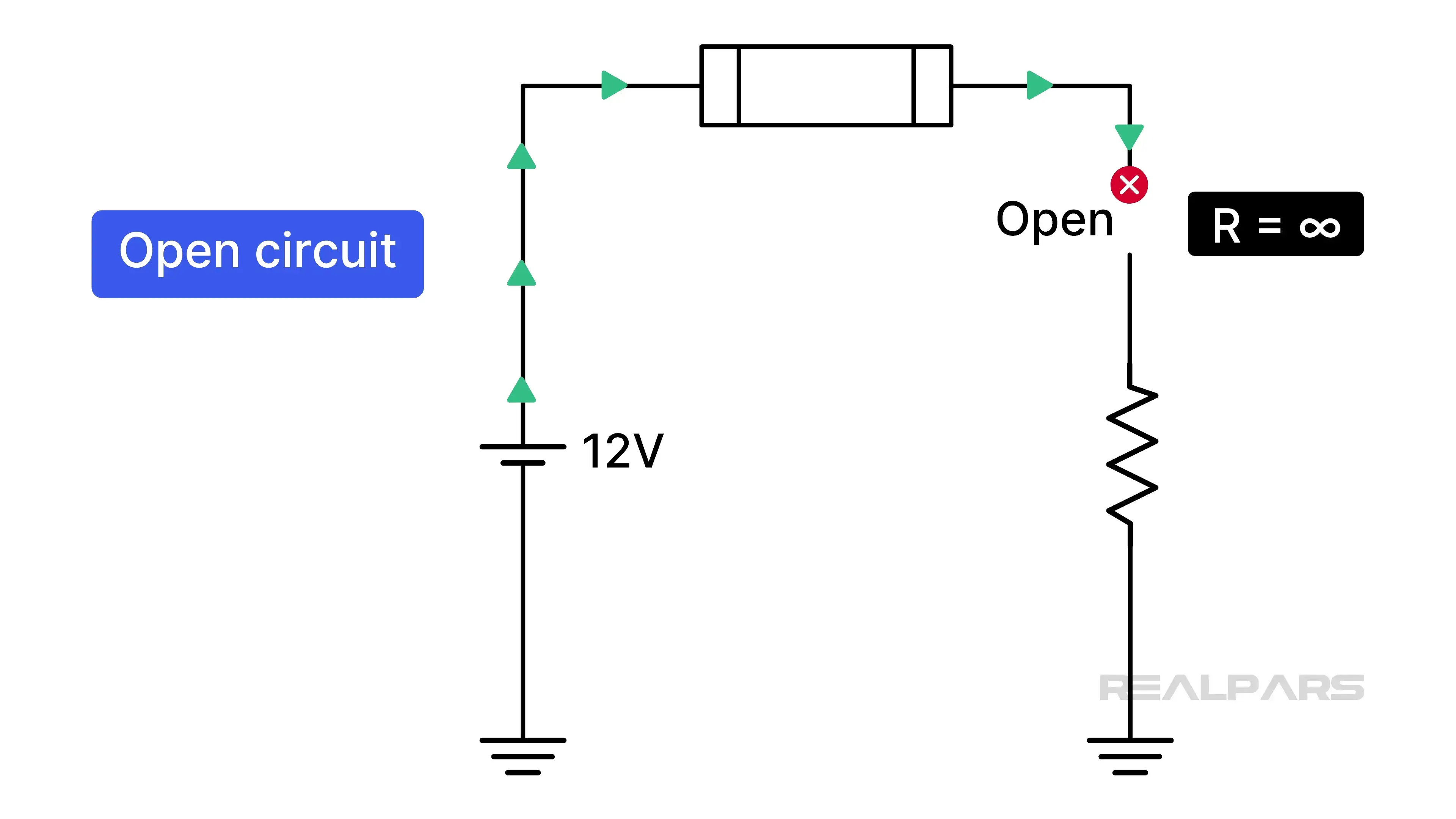
Let’s start with the open circuit. An open circuit interrupts the current path, preventing the flow of electrons. In other words, it stops all current flow. An open circuit exhibits extremely high resistance — effectively infinite.
There are many causes of open circuits, but the most common are failed or burnt-out components. An eagle eye and nose will often detect burnt components by their appearance and smell. Other culprits include broken conductors and loose terminals.
Open circuits are best found with a voltmeter in an energized circuit, and we will show you how.
Short circuit
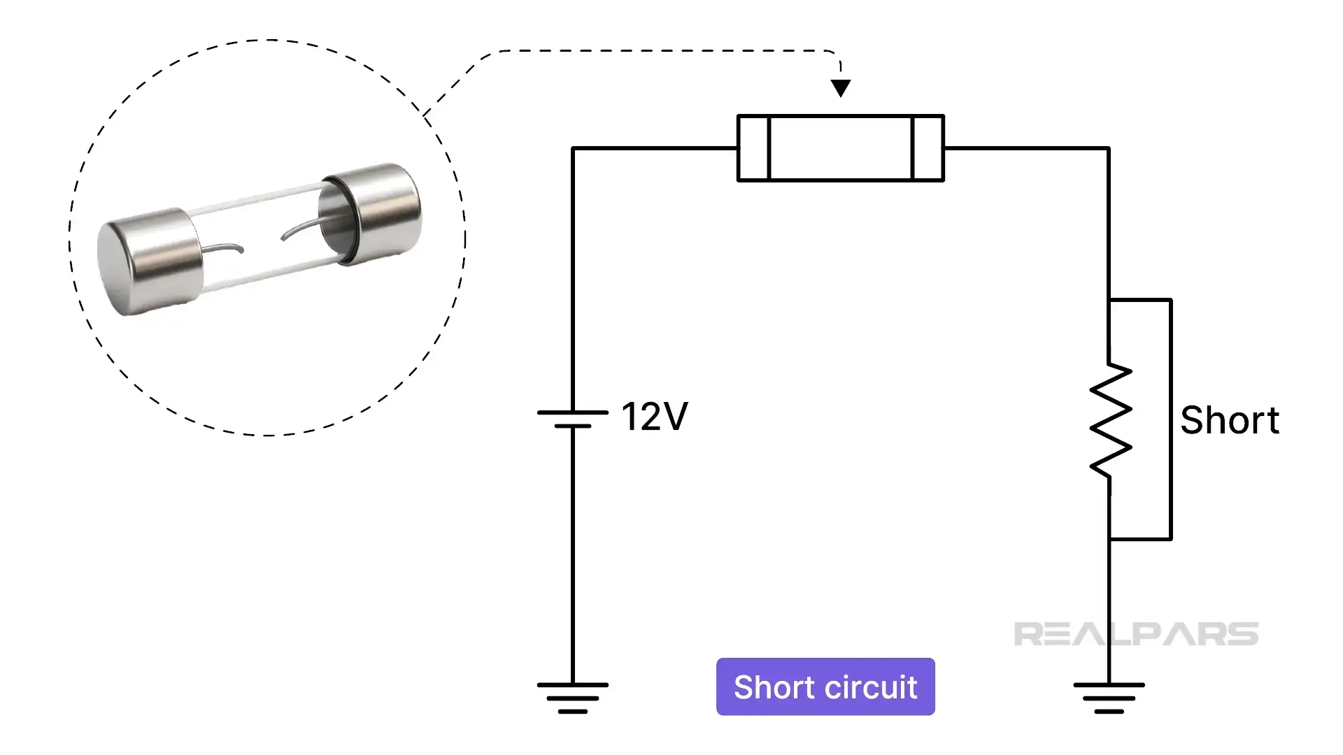
Short circuits are nasty and often difficult to find. A short circuit exhibits very low, near-zero resistance, creating an unintended high-current path.
They are caused by factors such as careless placement of conducting tools, conductive materials touching due to insulation failure, moisture, or other conductive debris. Very few components fail and remain shorted, but some can, for example, a Zener diode.
Short circuits usually result in an open fuse or a tripped protective device, often eliminating the use of live-circuit voltmeter tests. They are best confirmed by resistance testing, which requires following safety practices for ohmmeter use and, where required, lockout/tagout procedures.
How to troubleshoot an open circuit
OK, let’s put on our troubleshooter’s hat and investigate an Operator’s fault report. An Operator reports that a specific process is not being controlled.
After some initial sleuthing of the HMI and PLC logic, everything appears to be operating correctly from a software standpoint. So, we decide to perform specific hardware testing.
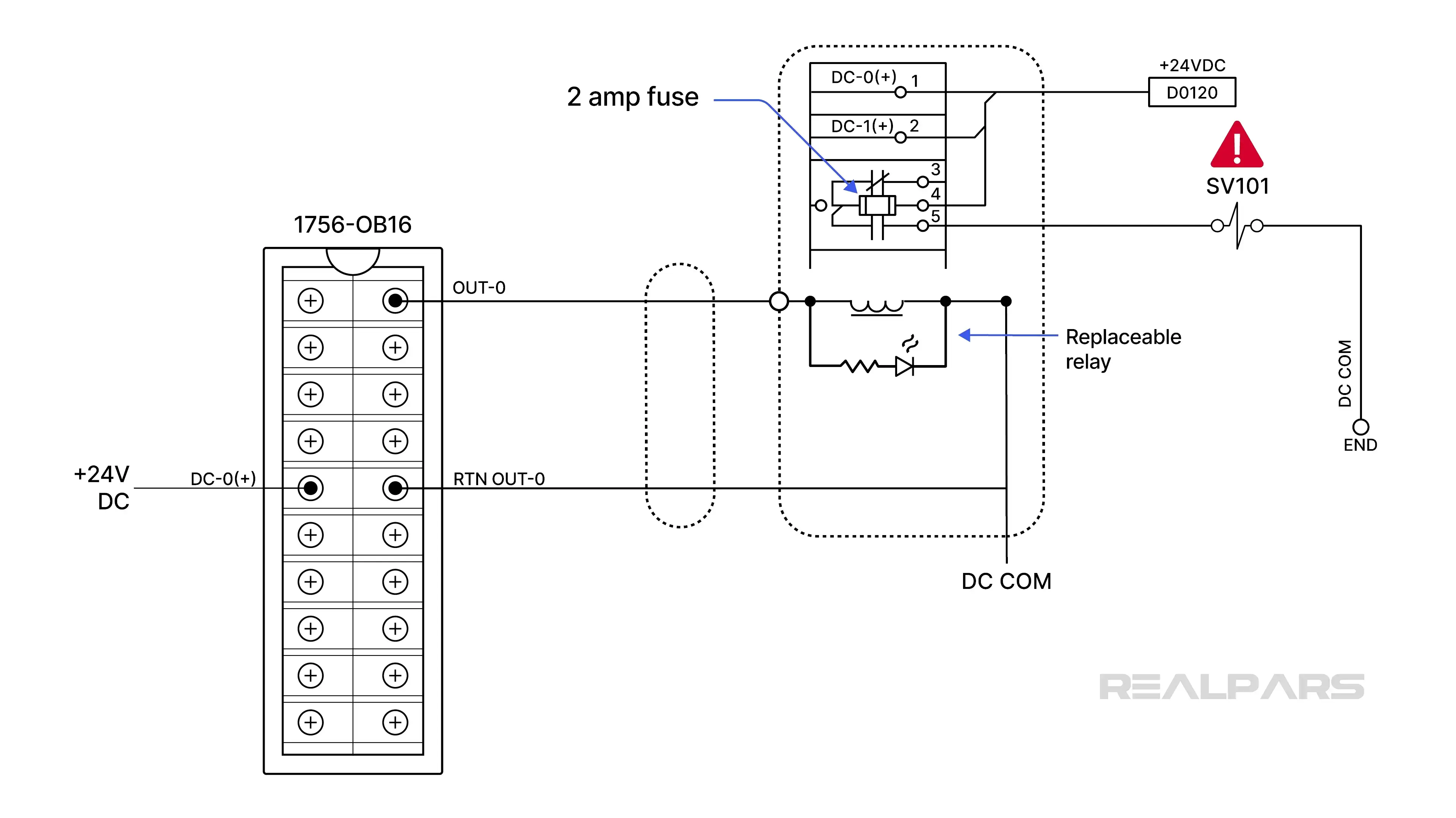
Digging into the documentation, we identify a sourcing-type digital output module connected via a field cable to a 16-point relay interface module. One of the relays on this module ultimately controls the solenoid valve SV101. Each relay channel has its own 2-amp fuse and replaceable relay.
During visual inspection, we observed that the PLC OUT0 LED and the relay K0 indicating LEDs are ON. The PLC is commanding the output, and the relay coil appears to be energized as expected.
There are many possible faults, but the most likely are an open fuse, an open solenoid, or a broken wire.
Alright… if we don’t see anything obvious, it’s time to take some measurements with our digital multimeter.
Many troubleshooters might start by testing the fuse for continuity, assuming it might be open. That requires interrupting the circuit and removing the fuse.
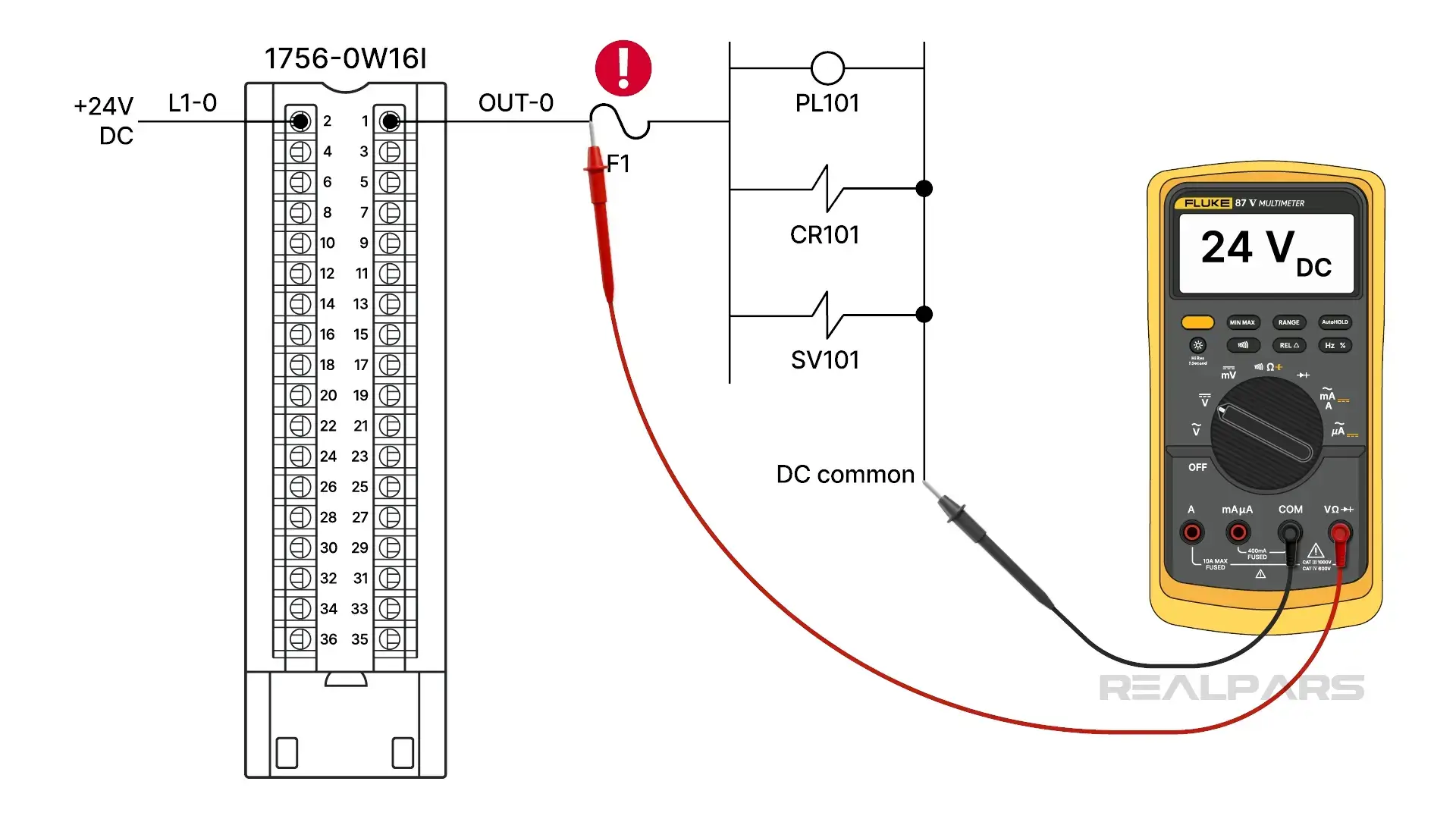
There is a better and faster way to isolate a potential open circuit. We’ll use the divide-and-conquer, half-split method. To start, we connect the voltmeter black lead to DC COM as a reference point for all voltage measurements.
Our first voltage measurement is at terminal 5 of TB1 on the relay interface module. If we measure +24 volts at terminal 5, that rules out the fuse and the K0 normally open contacts.
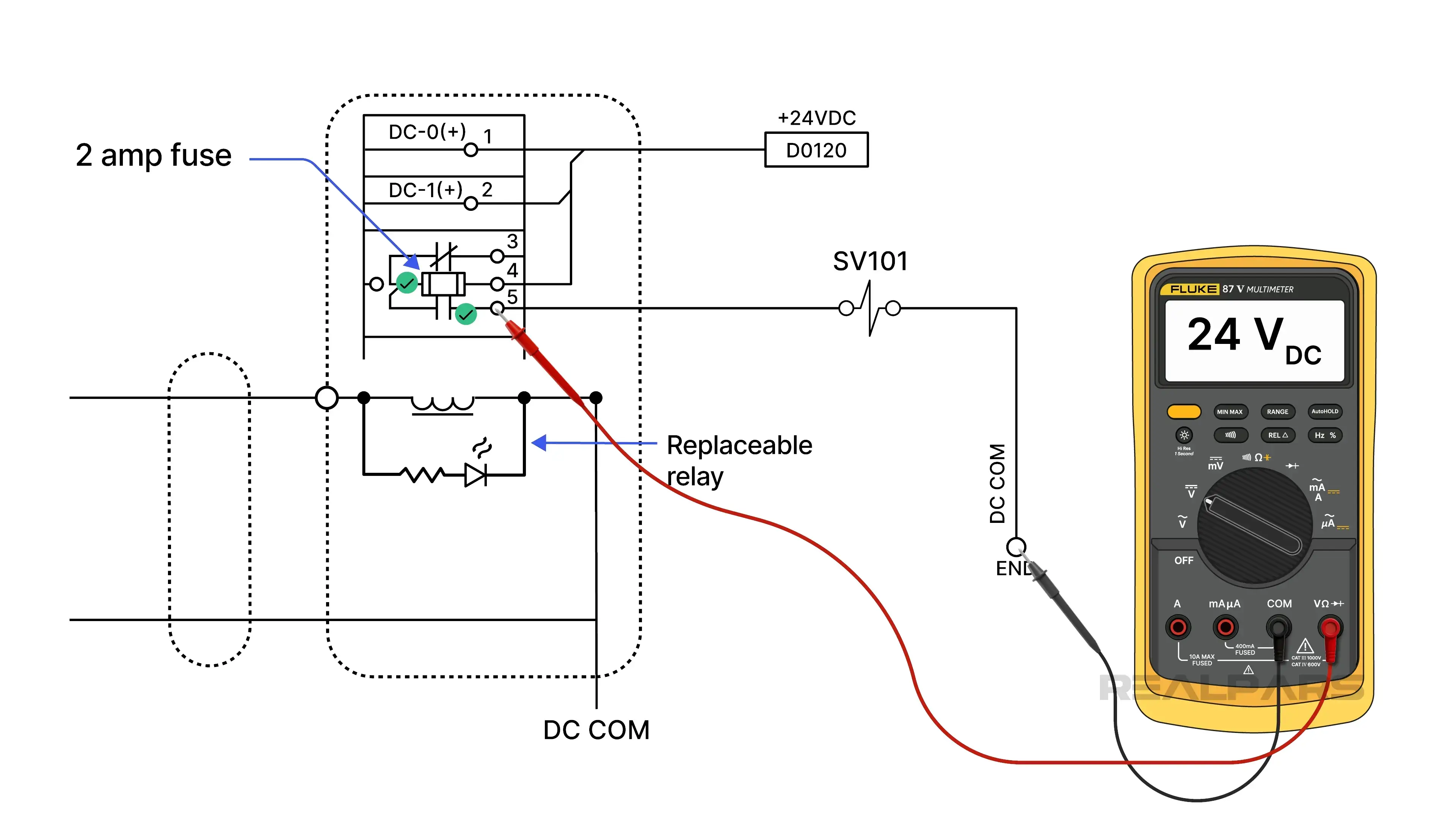
An open fuse or relay contact would produce 0 volts at terminal 5. Why? If the fuse were open, the entire +24 volts would be dropped across it. And the same with the K0 normally open relay contacts.
So, a single voltage measurement eliminates several possible faults and moves us in the right direction.
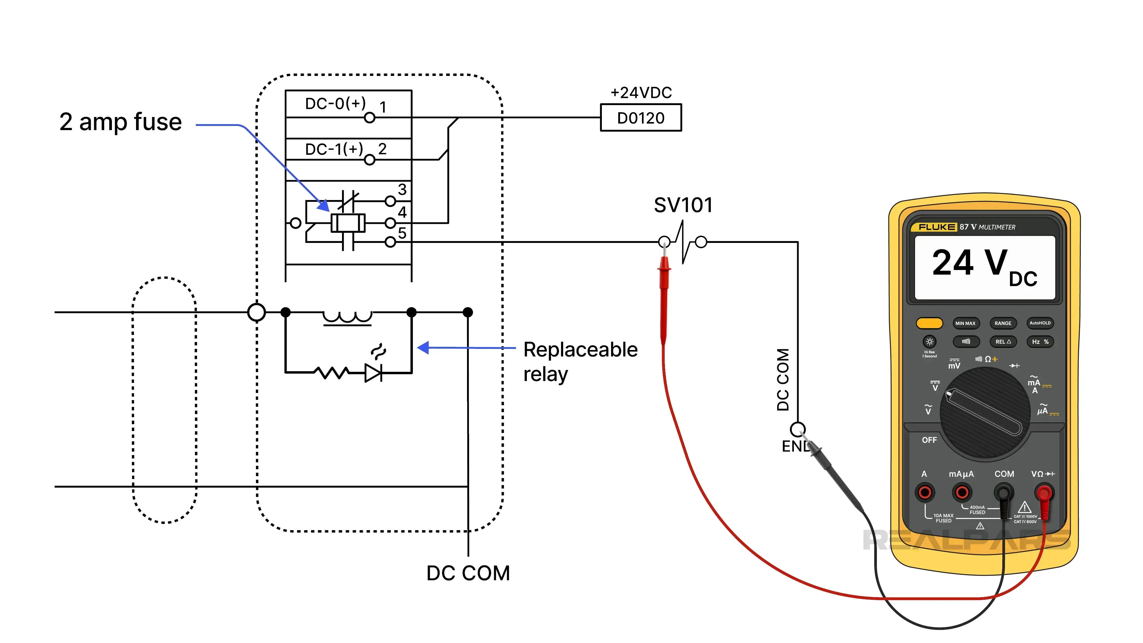
A voltage measurement on the line side of SV101 will indicate whether there is a broken connection between the relay block and the solenoid.
A reading of 0 volts indicates an open circuit caused by a broken wire. If we measure 24 volts, a second measurement will tell us whether SV101 is open or if we have a broken connection to the DC common.
A voltage measurement on the DC common side of SV101 will indicate whether there is a broken connection between the solenoid and the DC common. A 0-volt reading indicates an open SV101.
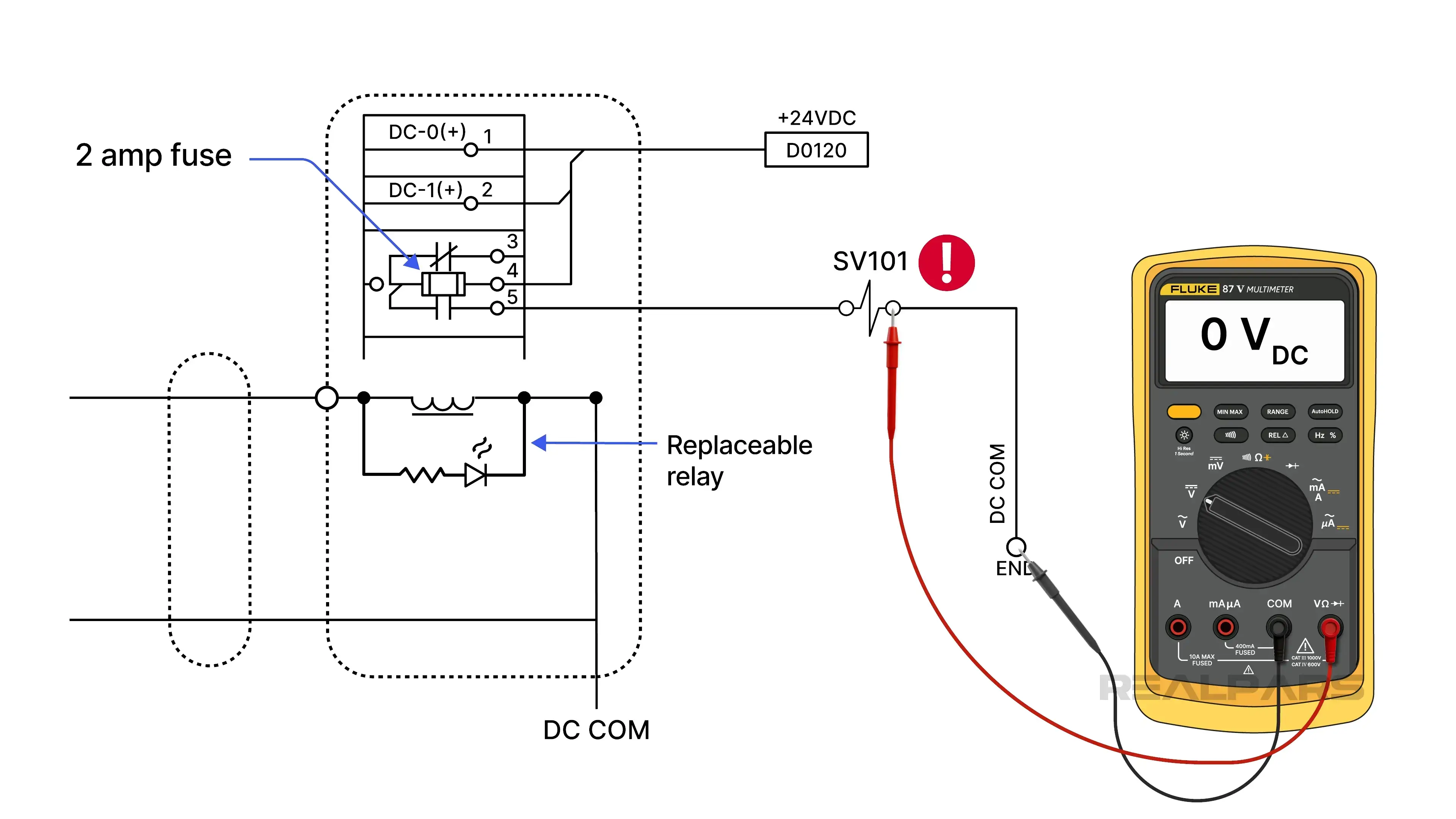
If we measure 24 volts, we have an open circuit between SV101 and DC common.
How to troubleshoot a short circuit
Let’s move on to a circuit with a short.
A single dry-relay digital output from a PLC drives three field devices wired in parallel.
All three loads share the same 2-amp fused 24 VDC supply. Our loads include a pilot lamp, a control relay, and a small solenoid valve.
In our fault scenario, the pilot lamp is off, and the electromagnetic devices are de-energized.
Everything appears to be operating correctly on the software side. During visual inspection, we observed that the PLC OUT0 LED is ON. The PLC is commanding the output devices to energize and the pilot lamp to turn ON.
We measure 0 volts on the load side of the fuse and assume it is blown.
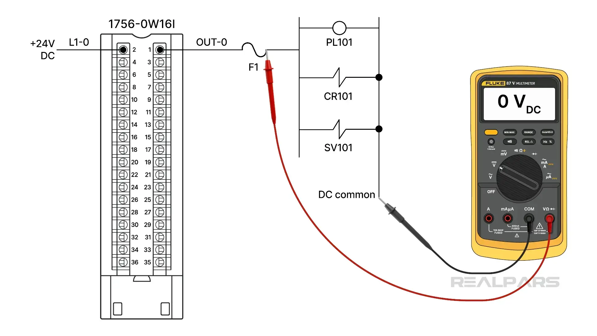
We measure +24 volts on the line side of the fuse, verifying a blown fuse. Replacing the fuse is not an option until we verify the cause. A short circuit would do it!
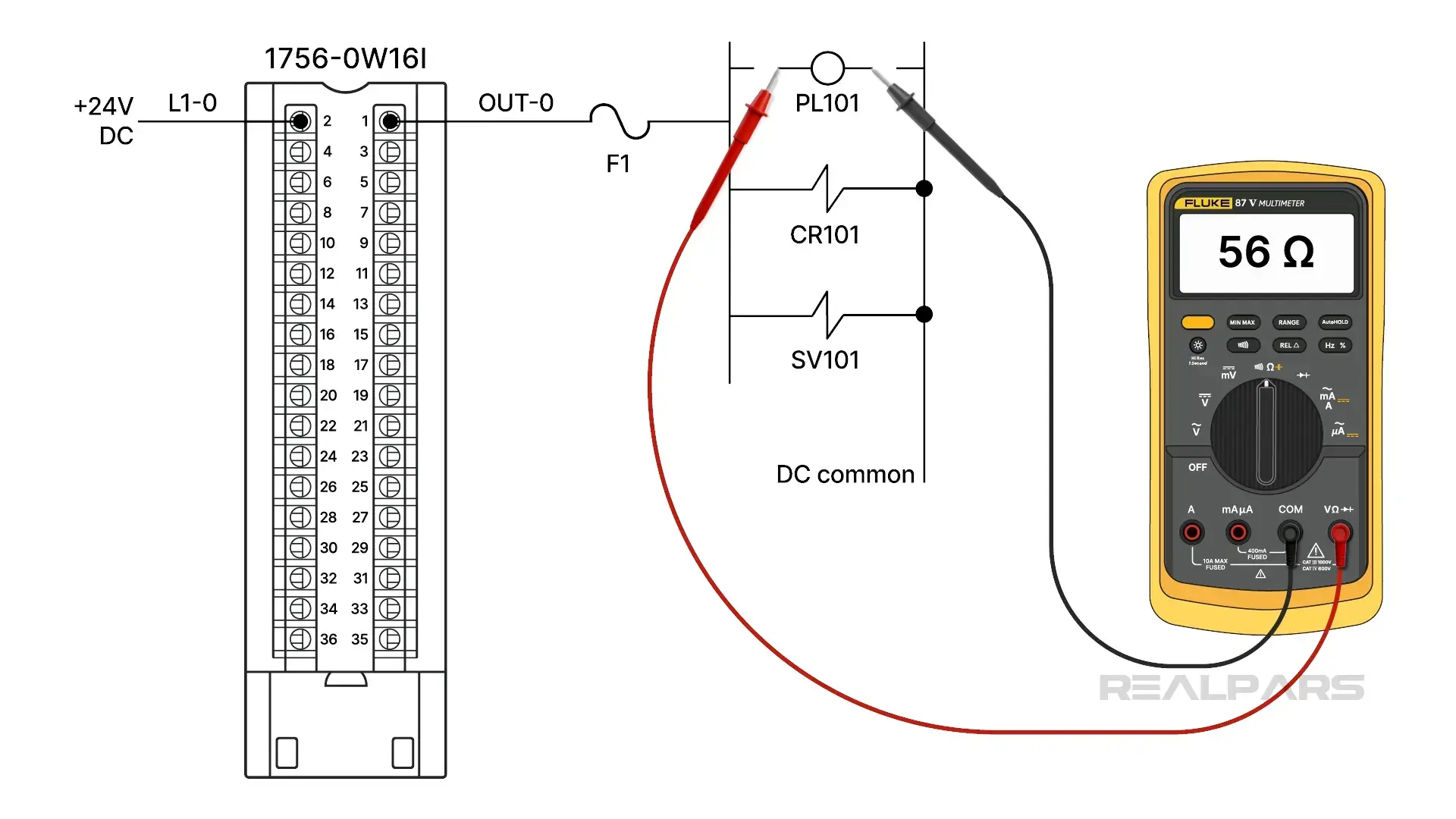
There are no further voltage readings we can make to assist us. Now it’s time to switch to Ohms. When we place an ohmmeter across the pilot lamp, we measure zero ohms. Well, that must be the shorted component causing the fuse to blow.
Not so fast! You will get the same resistance measurement across each load because they are all in parallel! We have no alternative now but to isolate each load one at a time until we find the shorted component.
This process is usually not easy because it often involves removing wires from terminal blocks or cutting actual lead wires. It’s a process of elimination.
We’ll start with the easy-to-remove pilot lamp. Its measured resistance is 56 ohms, so that’s not the problem.
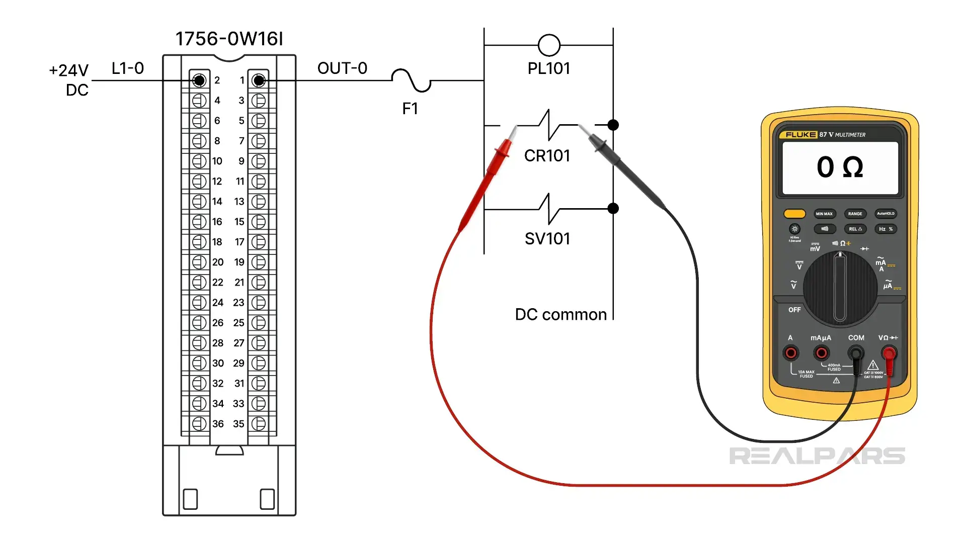
Next, we’ll isolate the control relay. Its resistance is zero ohms. We’ve found our culprit.
Okay, so now you’ve found the fault. You are a hero! But your job isn’t done yet. The failure should be documented. This is the part that most of us dislike the most. Paperwork. It’s essential to document what failed, when it occurred, and what symptoms were observed.
A key question is why the failure occurred in the first place. Understanding the underlying cause enables corrective actions to prevent it from happening again and causing more unnecessary downtime.