
In this article, we examine electrical continuity and diode testing using a digital multimeter, also called a DMM.
We’ve all heard the familiar multimeter beep when doing a continuity test, but what does it signify? We will also explain how a diode functions and demonstrate how to perform diode tests correctly using a DMM.
Let’s kick things off with a discussion about what Continuity and Resistance are. It’s tricky to test for Continuity if we’re unsure what it is.
The vendor Fluke, which manufactures a series of digital multimeters, states, Continuity is the presence of a complete path for current flow.
What about resistance? Fluke also states that Resistance is a measure of the opposition to the flow of current in an electrical circuit.
That’s where the concept of continuity becomes a bit fuzzy. Why fuzzy? Because what is the resistance of a circuit with a “complete path for current flow?”
Is it zero ohms? Is it 100 ohms? Is it 500 ohms? We need to understand what the multimeter is actually doing during a continuity test and how to interpret the audible beep.
Continuity & troubleshooting example
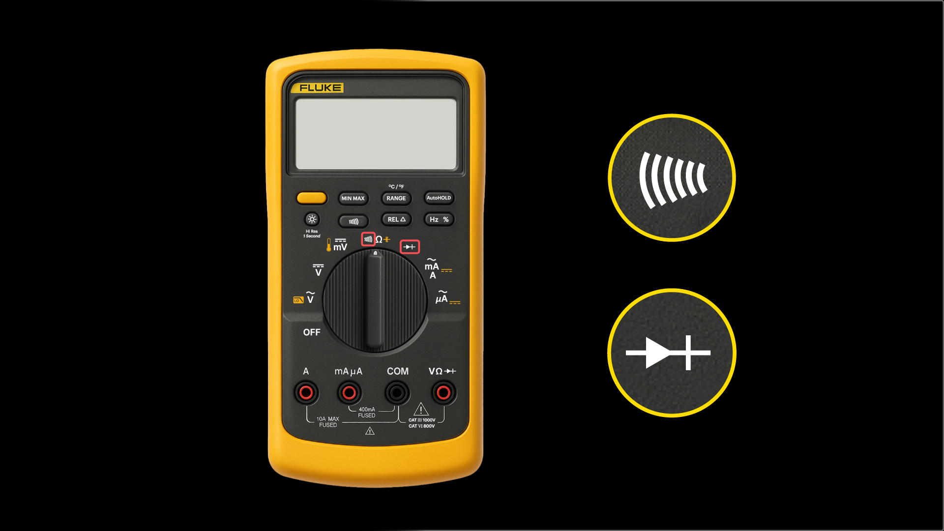
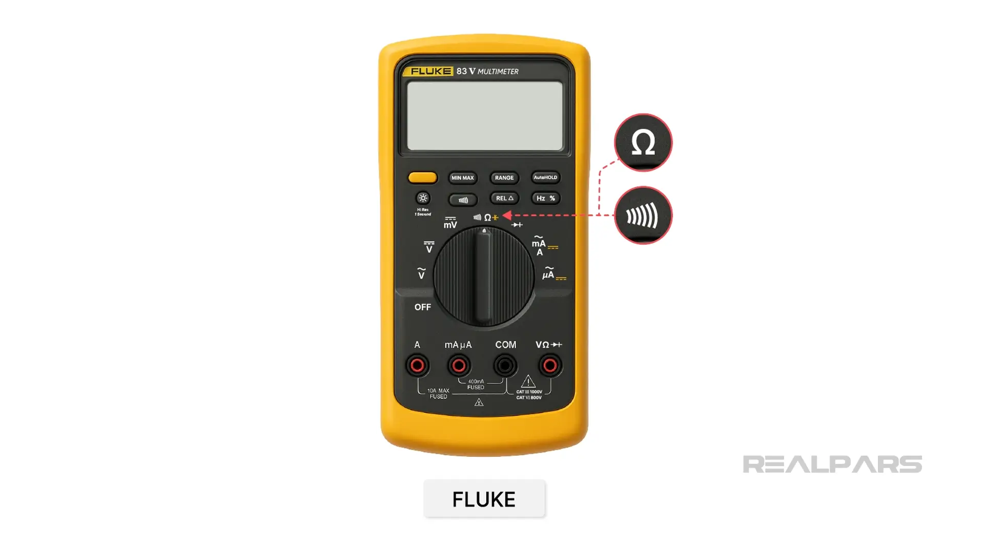
The Continuity multimeter position symbol varies by vendor, but you’ll likely see the sound wave symbol used more than others. For example, the Fluke 83 DMM uses a sound wave symbol.
You may notice that the OHMS symbol is at the same selector position as Continuity. This is common, as a continuity measurement is a type of resistance measurement.
Other vendors, such as Klein Tools and Greenlee, share a DMM selector position with Continuity and diode test functions. This is also very common.
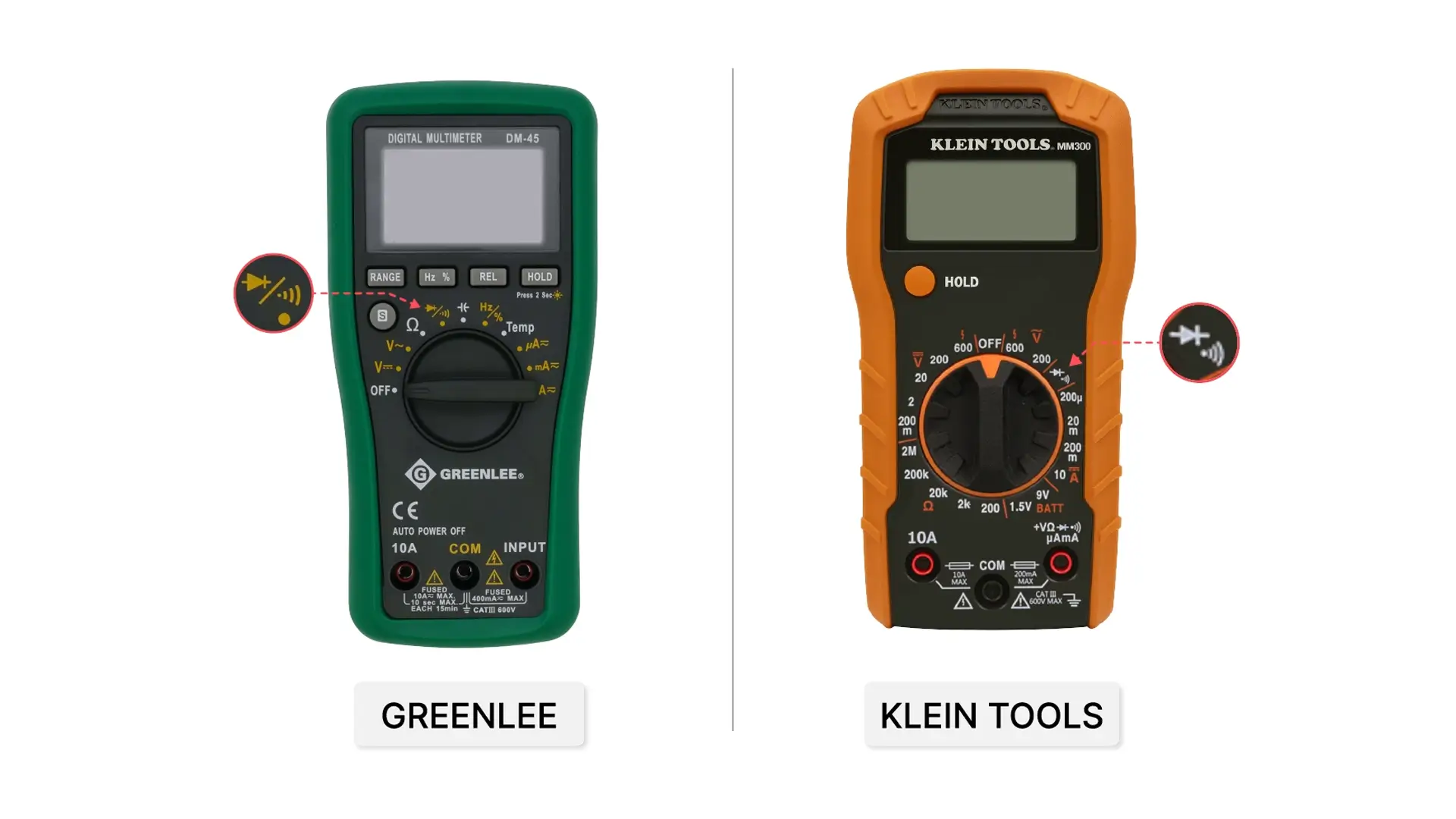
We’ll investigate diode testing later in this article.
Ok, let’s go back to our discussion about continuity and resistance.
We’ll examine a possible troubleshooting scenario to illustrate the distinction between continuity and resistance testing.
A suspected faulty SPST toggle switch is located on a control room console. Unfortunately, due to the awkward location, it is not possible to place the DMM leads on the switch terminals and view the multimeter display simultaneously.
Therefore, it appears that the solution is to place the DMM in the Continuity position and listen for the beep. Of course, we follow all the rules for using a DMM to measure continuity and resistance.
During our test, we found that when the switch is open, the DMM is silent, and when the switch is closed, the DMM beeps.
Do these tests indicate that the switch is functioning properly and not the source of the problem?
Remember, we can’t actually see the DMM screen during the measurements!
The normal switch resistance should be close to zero ohms. So, Can we safely assume the closed switch is close to zero ohms if we hear the beep?
Unfortunately, the beep only means that a complete circuit is present for current flow. The beep tells us nothing about the resistance of the switch. In fact, the multimeter may produce a beep up to a measured resistance of 50 ohms! We don’t want a switch with a resistance of 50 ohms!
In fact, most DMM specifications state a finite continuity threshold value at which the device beeps, depending on the range setting.
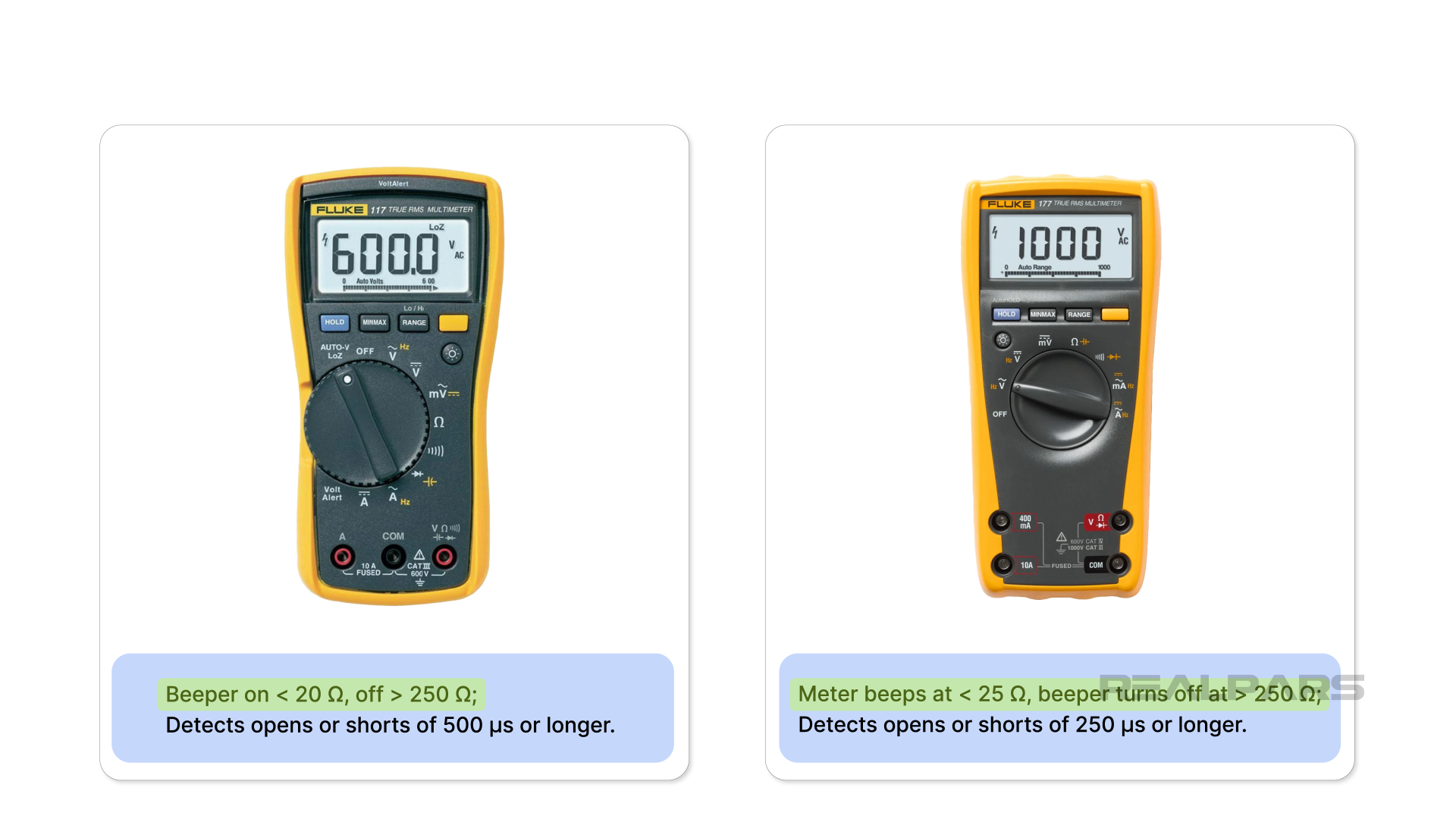
When you have a few spare minutes, dig out the user's manual for your DMM and see if you can find the continuity threshold value. If you can’t, experiment with a potentiometer.
In summary, it is easy to misinterpret a beep. It is important to know that the beep does not indicate a zero-ohms condition, but rather that it means a complete circuit, as high as 50 ohms, may be present.
In our troubleshooting scenario, the beep might lead us to conclude that the switch is not at fault, and lead us down a troubleshooting rabbit hole searching elsewhere.
Understanding Diodes
We’ll now proceed to Diode testing.
A diode is an active semiconductor device that, when properly biased, only allows current to flow in one direction.
OK. That’s a mouthful. Let’s break that down.
Imagine a plumbing system with a one-way check valve that only allows water to flow in one direction.
In most applications, it serves as a safety device to prevent water from flowing backward by slamming shut.
A diode works in a similar way, but instead of water, it involves the flow of electrons, or current. Sometimes, a diode is used as a safety device, but it also has numerous other applications.
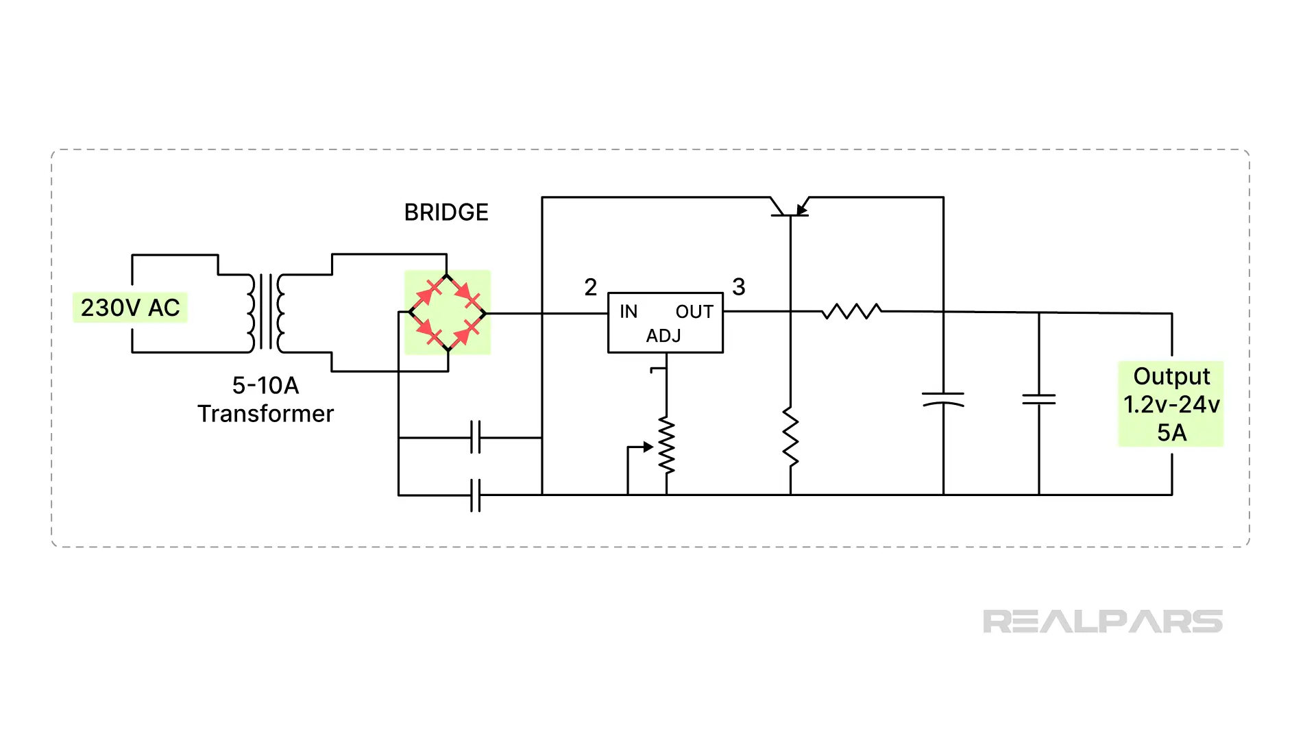
Diodes are used in DC power supplies as rectifiers to convert AC to DC voltages. A common bridge rectifier consists of four diodes.
A diode is often used to prevent damage to a device by inserting a diode to block possible reverse current.
Flyback Diodes are placed across inductive devices, such as relays and solenoids, to protect sensitive electronic equipment from large voltage spikes created when these devices are deenergized. Flyback diodes also protect against explosions in hazardous locations.
What about the reference to it being an active semiconductor device? That’s an important concept to understand because it plays a critical role in diode testing
Diode Biasing and Testing
What is biasing?
A diode has two terminals: the anode and the cathode.
Many signal and rectifier diodes have a stripe indicating the cathode terminal.
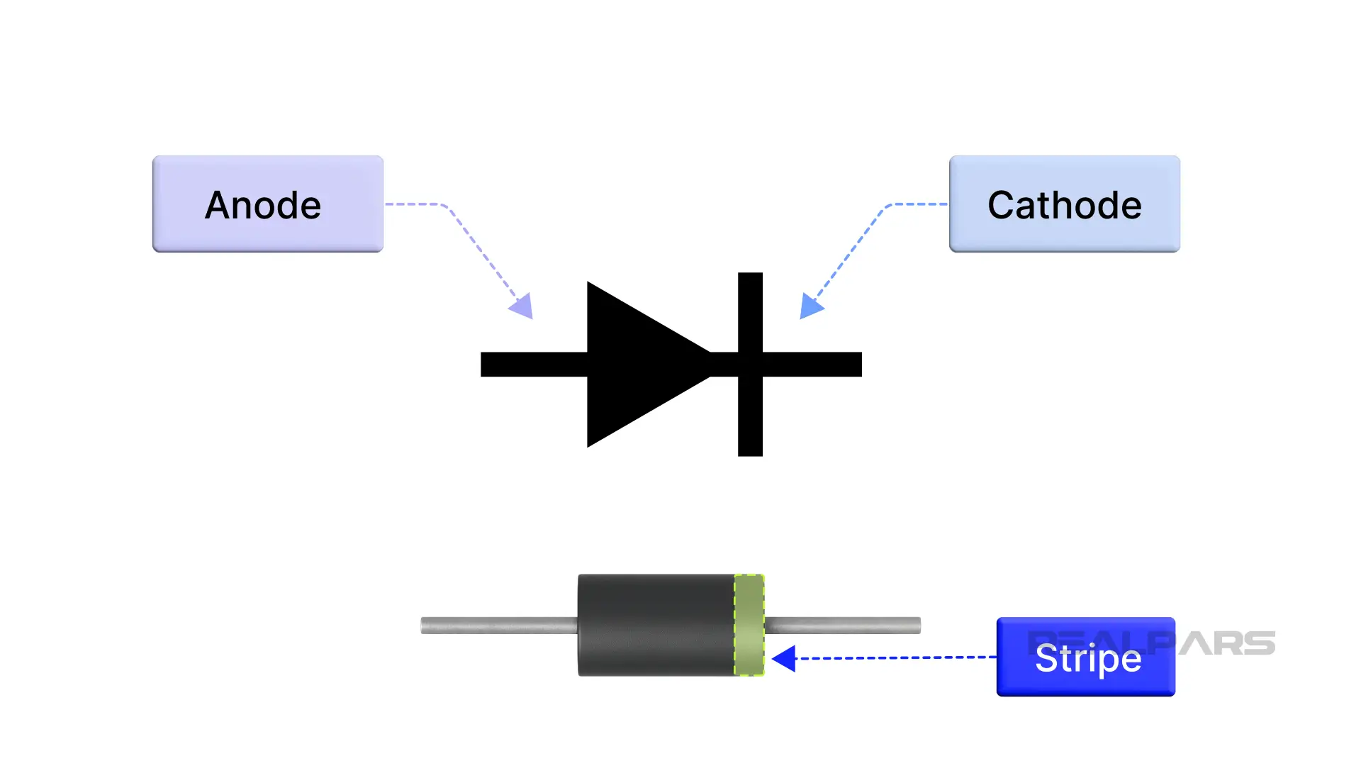
A diode allows current to flow only when the anode is more positive than the cathode, meaning it is forward-biased. When the cathode is more positive than the anode, the diode is reverse-biased, and no current flows.
Here’s a quick tip.
A functioning forward-biased silicon diode in a live circuit will have approximately 0.7 volts dropped across it. This voltage is referred to as the knee or barrier voltage.
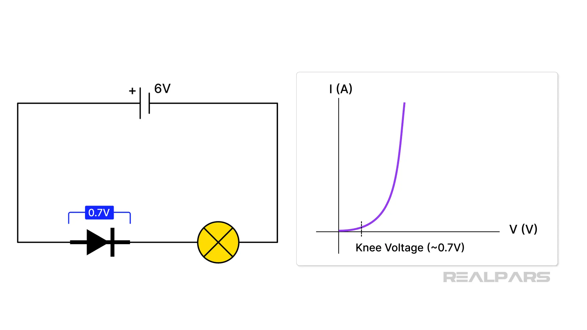
We’ll discuss this voltage a bit later in the article. You can easily measure this knee voltage with your DMM set to DC volts to confirm whether the diode is working.
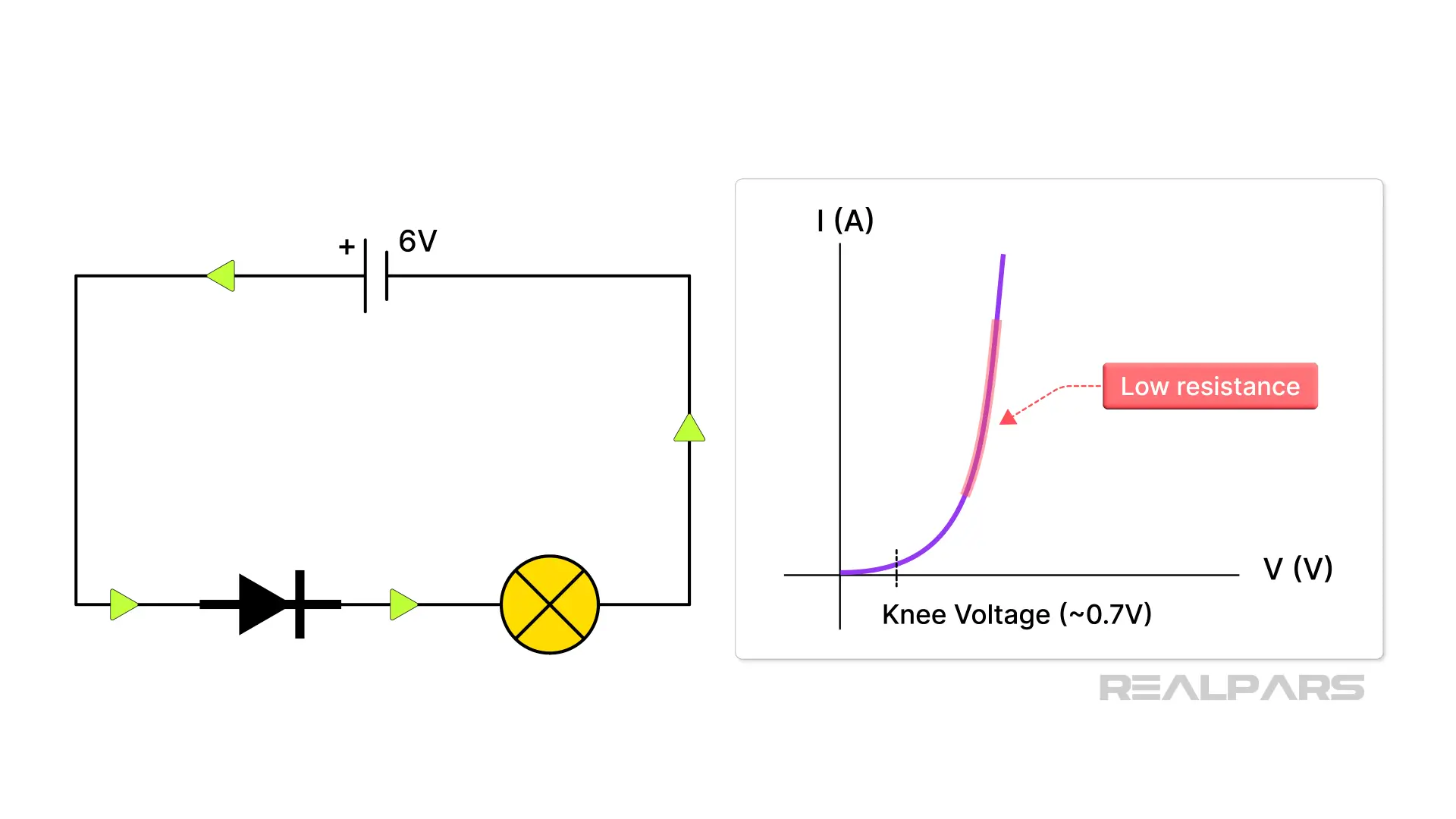
A diode does not always provide a low resistance path to current when you forward-bias it. In fact, its resistance remains quite high until the forward bias voltage rises enough to reach the knee voltage. At that moment, the diode offers a very low resistance to current flow.
Why can’t we use the Ohms function to test a diode?
In the Resistance or Ohms function, the multimeter applies a small voltage to the device under test. Most multimeters do not provide a high enough voltage to overcome a diode knee voltage.
Therefore, under a resistance test, the diode does not exhibit its expected low resistance characteristics, and the multimeter displays confusing and meaningless readings.
Okay, now that we’ve got that out of the way, let’s talk about using the Diode Test function on a DMM. The first step is to position the DMM in the diode test mode, which is typically indicated by a diode symbol.
Here’s the interesting part. The DMM’s diode test function works by sending a constant current through the diode and then displaying the voltage dropped across it.
In a forward bias connection, you’ll see a reading of approximately 0.7 V for a silicon diode.
With the multimeter leads reversed, the current can’t flow because the diode is reverse-biased, and the multimeter will read OL, or Open.
Wrap-Up
Ok….let’s summarize what we’ve discussed.
- Continuity is the presence of a complete path for current flow.
- The Continuity multimeter position symbol most often used is the sound wave symbol.
- It is easy to misinterpret a beep during a continuity test because the beep does not always indicate a zero-ohms condition.
- A diode is similar to a plumbing system with a one-way check valve
- The diode has two terminals: the anode and the cathode.
- Once the knee voltage is reached, a diode offers very low resistance to the flow of current.
- The DMM’s diode test function works by sending a constant current through the diode and then displaying the voltage dropped across it.
- A conducting forward-biased silicon diode will have approximately 0.7 V dropped across it.