
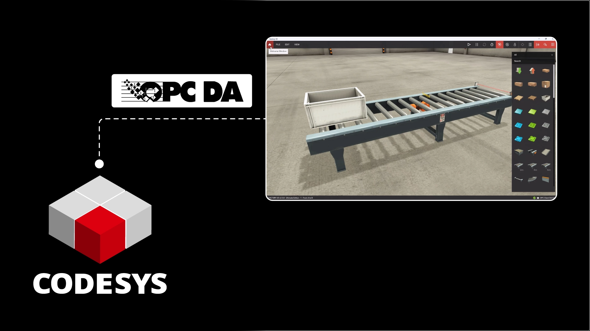
In this article, I’ll show you how to connect a CODESYS PLC to Factory IO using the OPC DA communication protocol.
Before we learn how to connect CODESYS to Factory IO using OPC DA, let me take a minute to introduce CODESYS, Factory IO, and OPC DA.
CODESYS
CODESYS is a vendor-agnostic controls runtime and development system. The development system is completely free to download and use, making it a popular choice for learning PLC programming.
You can learn how to download and install CODESYS on your computer by checking our article How to Download and Install CODESYS.
PLC manufacturers like WAGO, ifm, and Turck install the CODESYS runtime on their PLCs to make them into CODESYS-compatible devices. Any CODESYS application can be downloaded to a CODESYS-compatible device.
This is good for manufacturers because they can concentrate on their core competency of building innovative hardware.
It's also good for end users because they are not tied to a single vendor or a single piece of hardware. You can learn more about why CODESYS is important by checking our article What is CODESYS and Why is it important?.
Factory IO
Factory IO is a 3D simulation environment for PLC training. With Factory IO, you can connect a digital twin of a factory to a PLC to test code and visualize how your code would control a physical process.
Factory IO is a paid piece of software, but you can download a free trial of Factory IO using this link.
OPC DA
Finally, OPC DA, or Open Platform Communications Data Access, is a communications protocol used for accessing process data.
Using OPC DA is one of the easiest ways to connect a CODESYS PLC to a Factory IO scene.
Let’s see how to do that.
Use OPC DA to connect a CODESYS PLC to Factory IO
Create a project
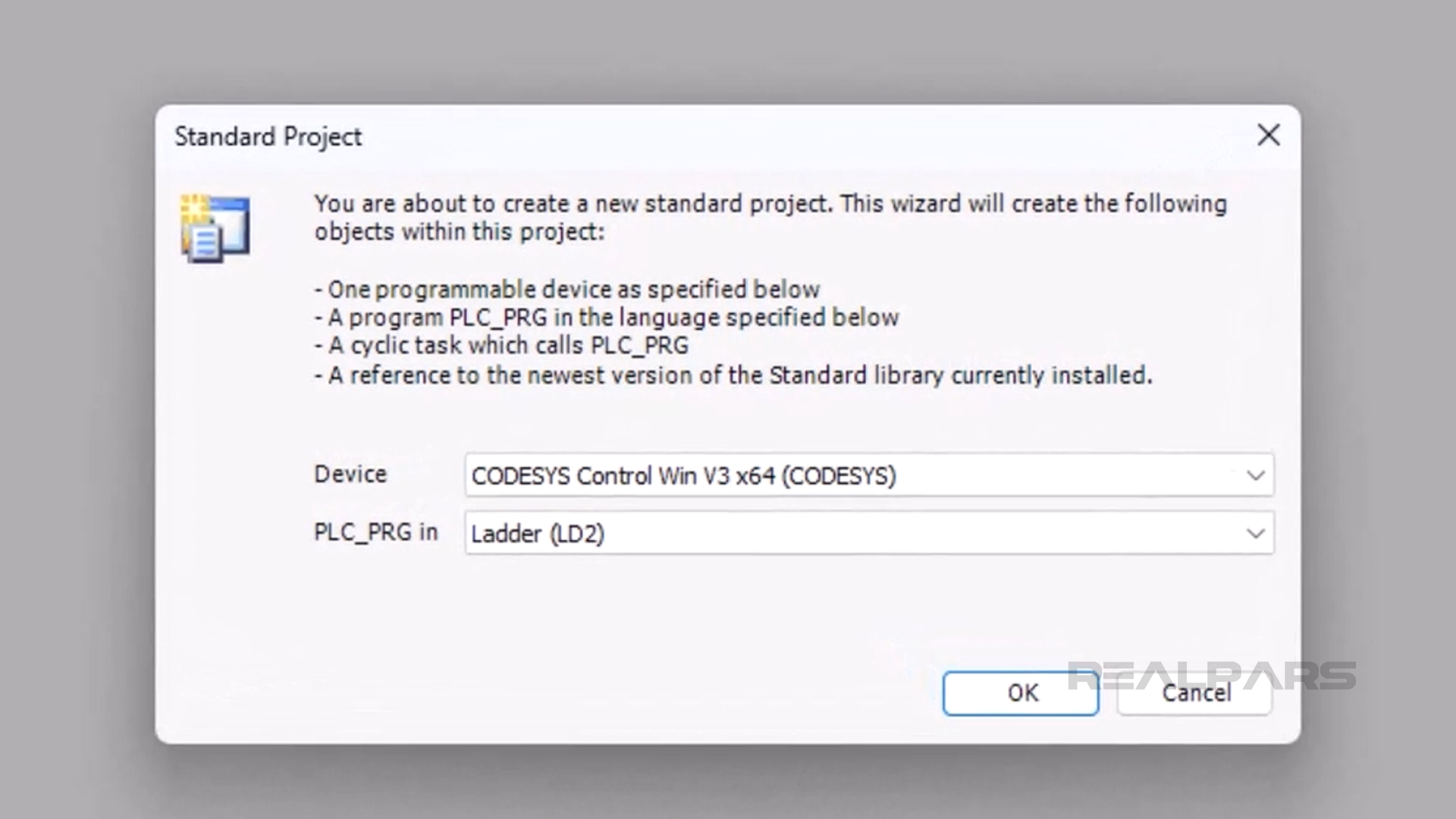
In CODESYS, I can create a new project using the Standard Project template. As part of the creation process, I specify that I want to use a CODESYS Control Win v3 device and Ladder as the programming language.
Configure variables
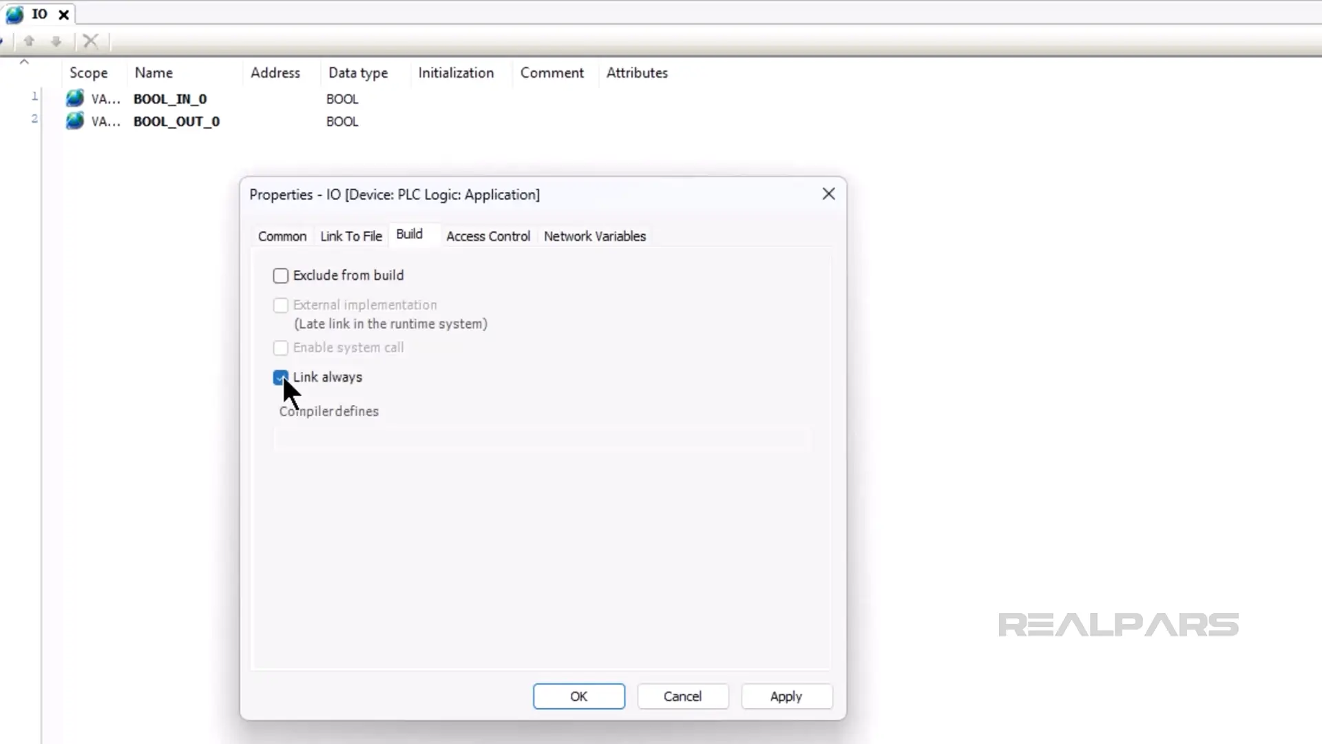
In the project, I add a Global Variable List to the application called IO and add the variables that we will use to exchange data with the Factory IO scene to the list.
After adding the Global Variable List, I right-click on the object and open its Properties. In the Build tab, I enable the Link always option to make sure that these Global Variables are available in my Symbol Configuration object.
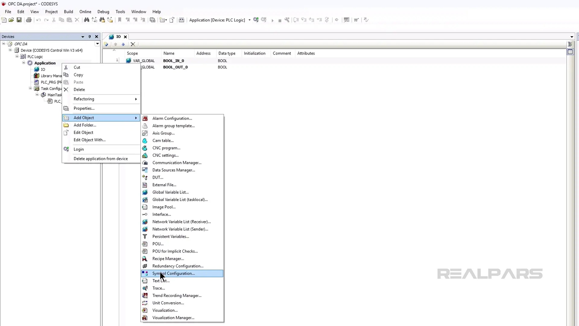
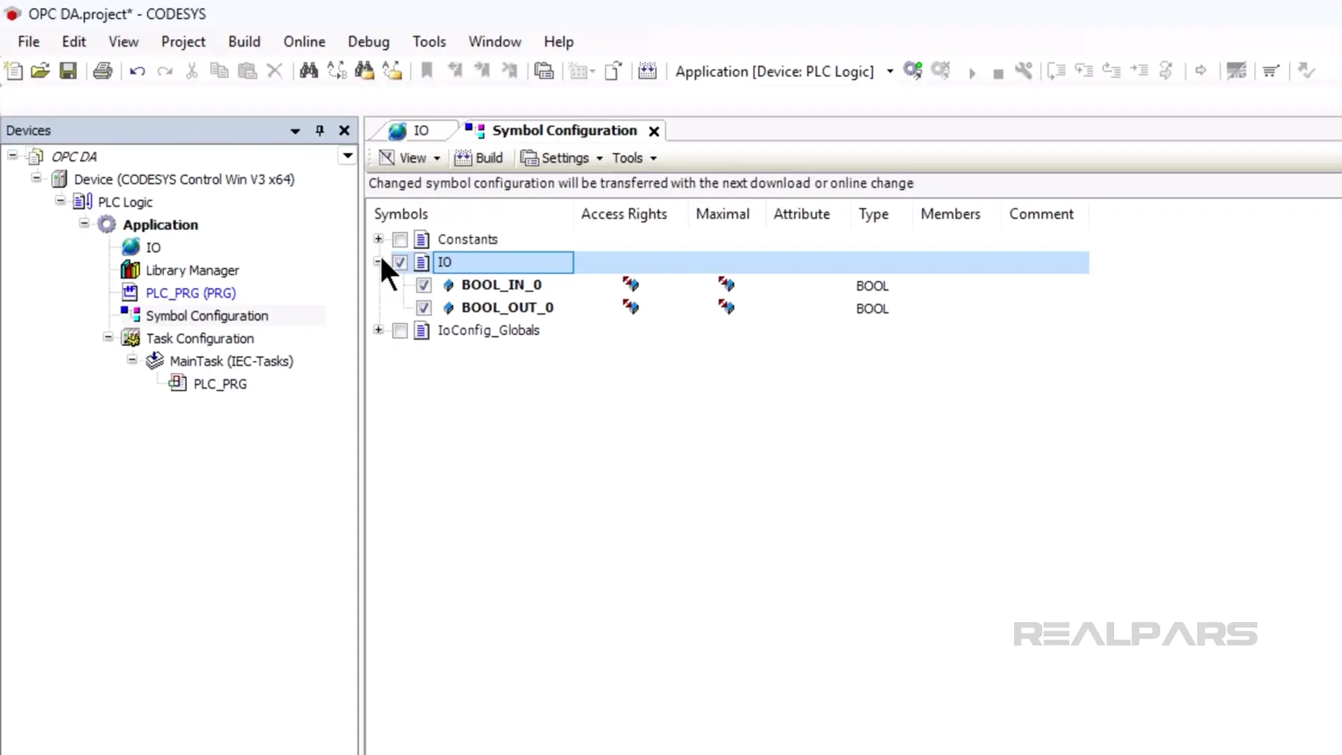
Next, I add a Symbol Configuration to the application to make these variables available to external applications like Factory IO.
After adding the symbol configuration, I build the project by clicking on the Build button.
After building the project, I check the IO symbols to allow external access to these symbols.
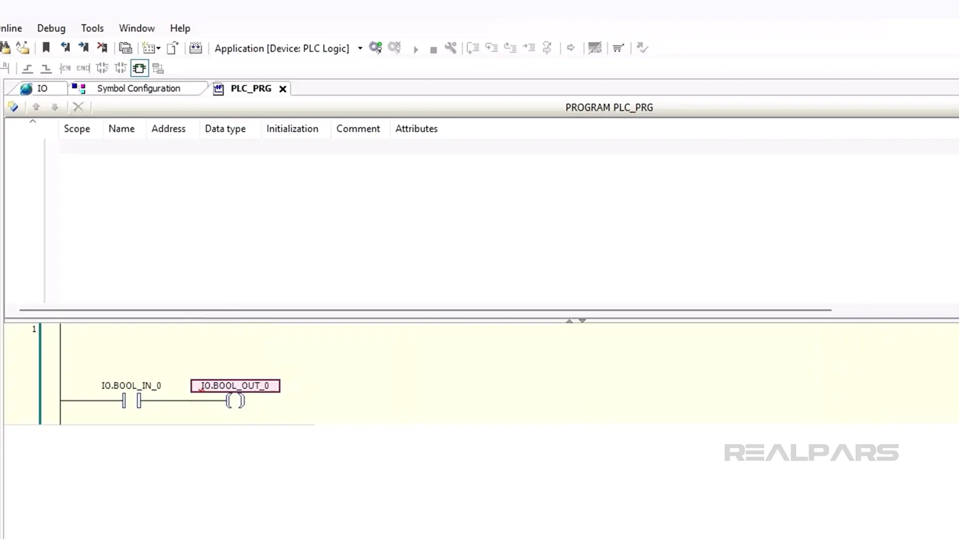
Write the logic
After configuring my Symbol Configuration, I open the PLC_PRG POU and write the simple logic for this application to run the conveyor motor when the normally-closed sensor is not triggered.
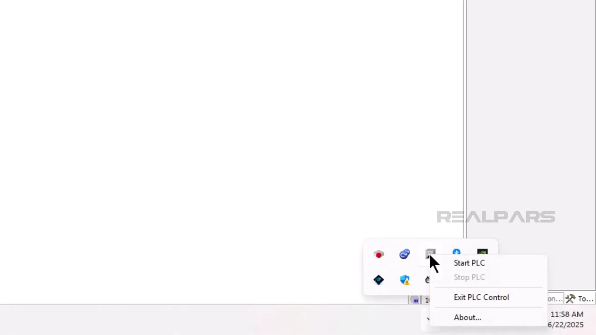
Download the project
Once the project is fully configured, I can start the CODESYS PLC from the system tray by right-clicking on the Control Win icon and selecting Start PLC.
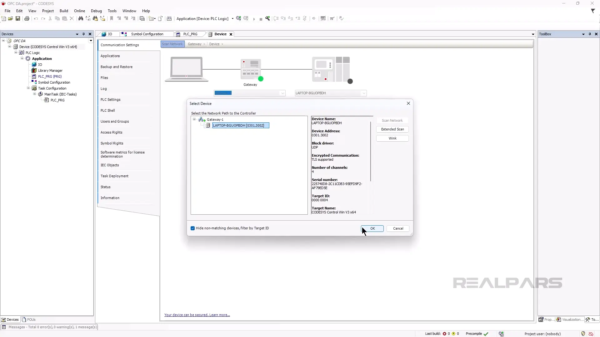
In the CODESYS Development System, I open the communication settings by double-clicking on the device and scan the network.
After scanning the network, I select the soft PLC running on my computer and click OK.
Now that the communication path is set, I can change the name of the device before downloading. I change the name of the device to DEVICE by clicking on Device and then Rename Active Device.
After changing the name, I download the project by clicking on Online and then Login.
Before downloading, I get a warning that User Management is required for the soft PLC, and click Yes to configure user management.
In the Add Device User dialog, I can specify a user name and password for the admin user of the device. After specifying the user name and password, I click OK to continue the download.
In the Login dialog that pops up, I can enter the new user name and password and click OK to download to the device.
After downloading, I can start running the project on the device by clicking on Start in the Debug menu.
Configure the OPC server
Now that the project is running on the PLC, we can configure the OPC server.
The CODESYS OPC DA Server is a paid product that is available to download from the CODESYS store with a 30-day free trial.
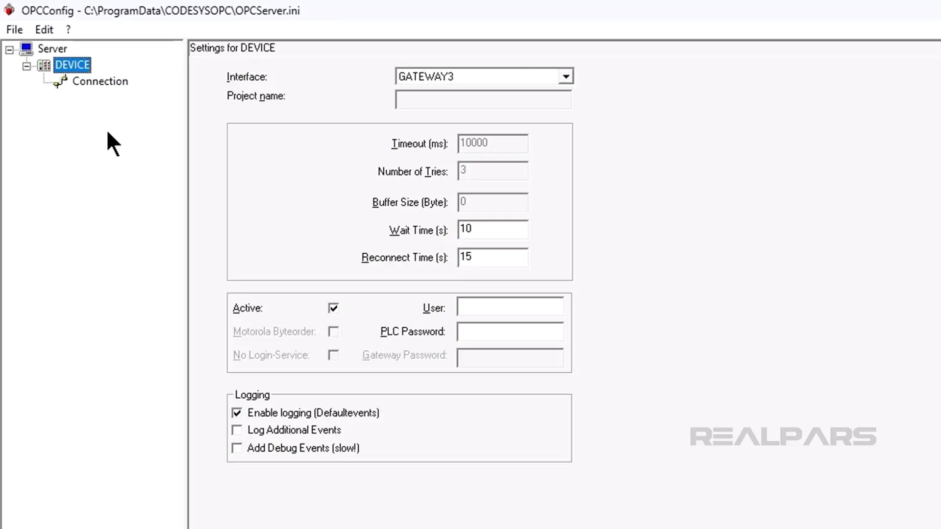
After installing the CODESYS OPC DA Server, launch the OPC Configurator application on your computer.
In the OPC Configurator, rename the PLC to the same name as the PLC in your CODESYS project and click save in the File menu to save your changes.
After saving, we can switch over to Factory IO.
Set Up Factory IO
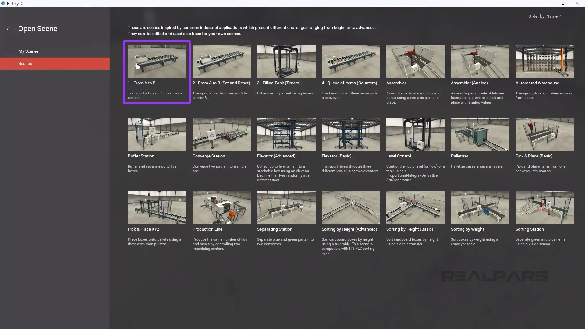
Next, I launch Factory IO on my computer and open the scene 1 - From A to B which we will use in this demo.
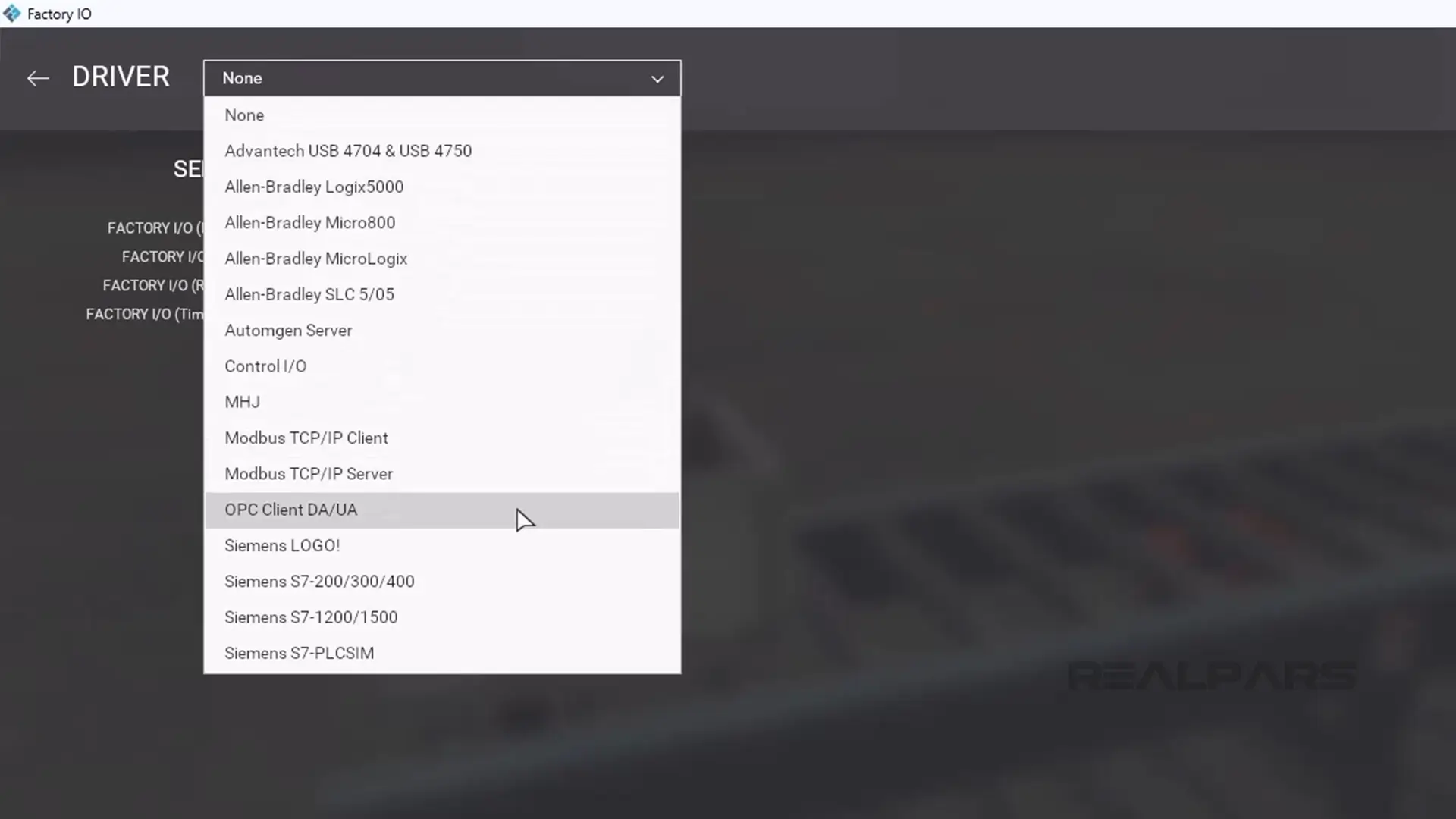
In the scene, I click on File and then Drivers to open the driver configuration.
From the dropdown list of available drivers, I select the OPC Client DA/UA driver.
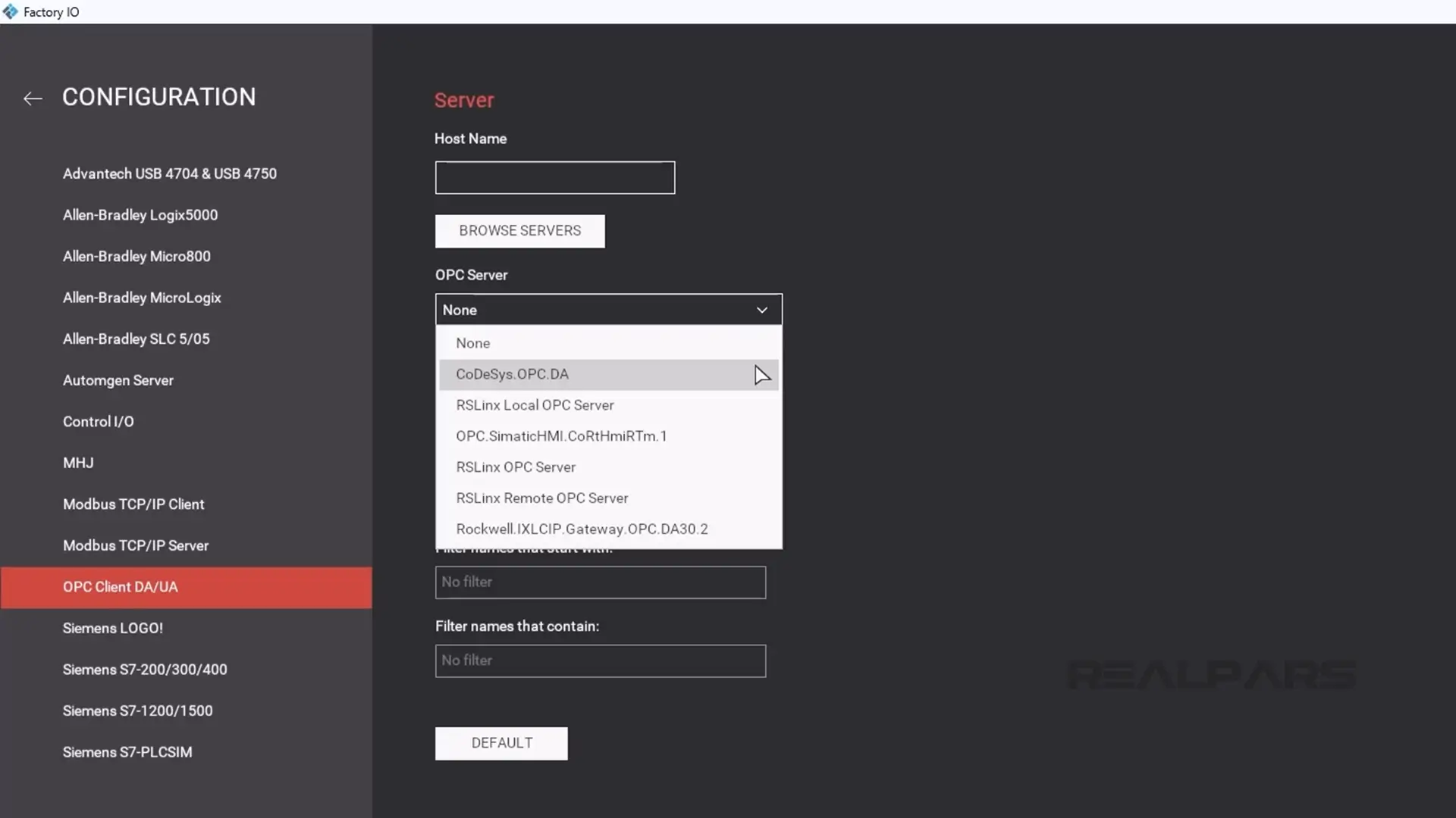
Next, I click Configuration to open the driver configuration window.
I select CODESYS.OPC.DA from the list of available OPC servers.
After selecting the server, I click Browse to find the nodes that are exposed by this OPC DA server.
Then I click the back arrow and map the sensors and actuators to the driver tags as shown here.
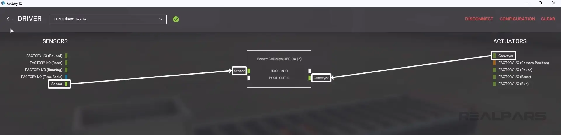
Finally, I close the driver window and run the scene to confirm that the communication is working.
As expected, the conveyor runs until the sensor is triggered by the tote.
Wrap-Up
In this article, I showed you how to connect a CODESYS PLC to a Factory IO scene.
If you want to learn more about how to program PLCs with CODESYS, RealPars has a number of courses on this topic.
RealPars Business members get access to these courses along with more than 120 other high-quality courses that can be used to train your team on demand to improve productivity and reduce downtime.
Learn more about RealPars Business by visiting realpars.com/business.