
You've just been assigned a work order to investigate a storage tank level issue. On the control room HMI, the level reads a steady 62%. On the plant floor, a field operator reports a sight glass level closer to 58%, though she says it’s hard to be certain because the glass is not very clear and the liquid is quite dirty.
This trend gap has been going on for weeks, so nobody has noticed the change from one day to the next. So, what's actually wrong? Is it a transmitter problem? Is the sensor at fault? Is there a wiring issue? Is it a faulty PLC input module? Or is the process measurement correct, and the sight glass leading misleading us?
In this article, we're going to talk about analog drift, why it happens, and how to methodically track it down and pinpoint exactly what is causing it.
First of all, analog drift doesn't trigger a usual alarm because there isn’t a detectable loop fault condition. The PLC happily accepts the signal it receives, scales it, and reports a representative value to the HMI.
Zero Drift and Span Drift
Anyone with instrumentation experience knows about Zero and Span because they’ve spent a lot of time adjusting each parameter on various instruments.
So, let’s talk about Zero Drift and Span Drift. Sensor and transmitter characteristics drift over time due to component aging, repeated heating and cooling, and electronic component degradation. That’s why scheduled calibration is performed to compensate.
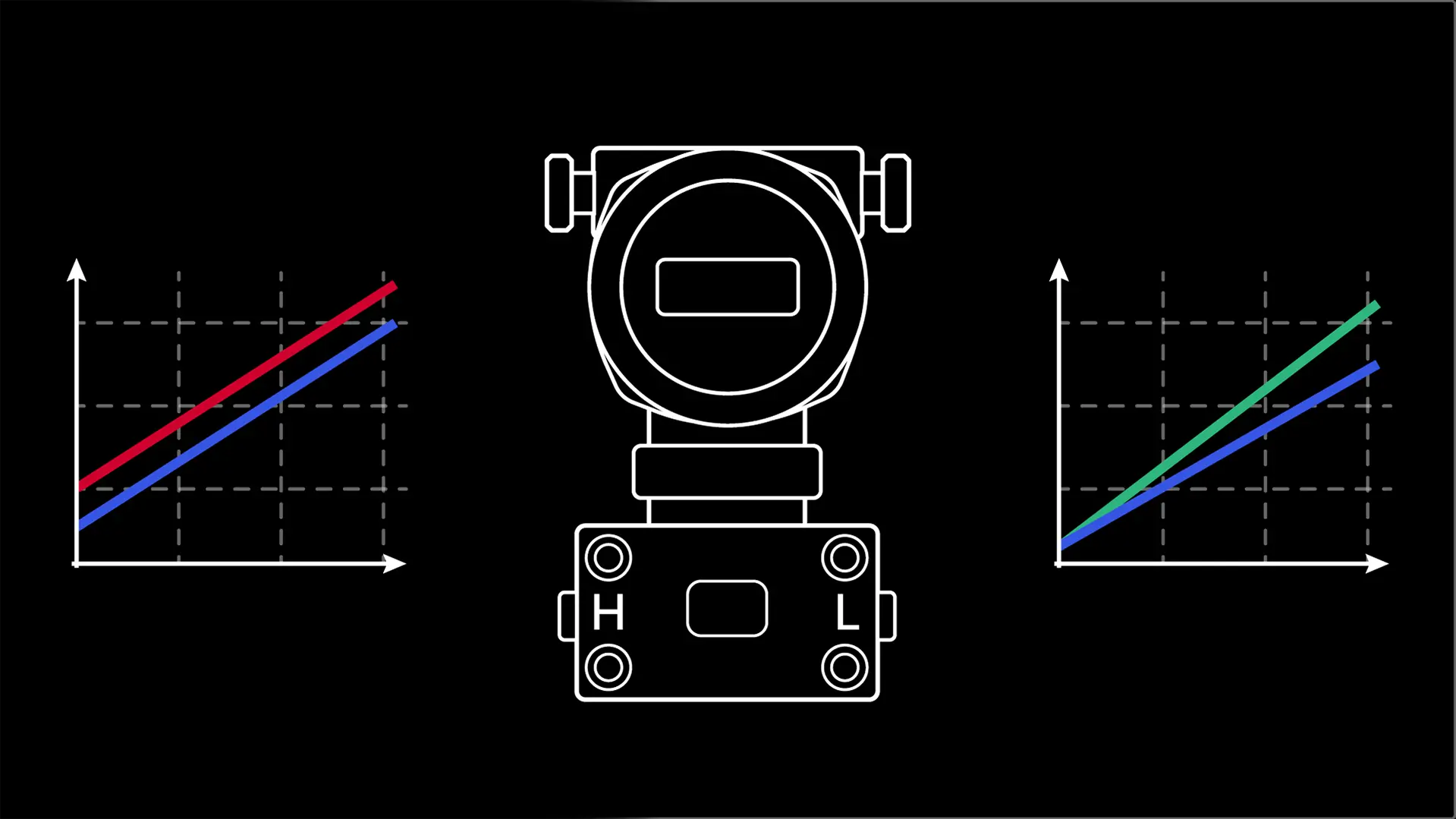
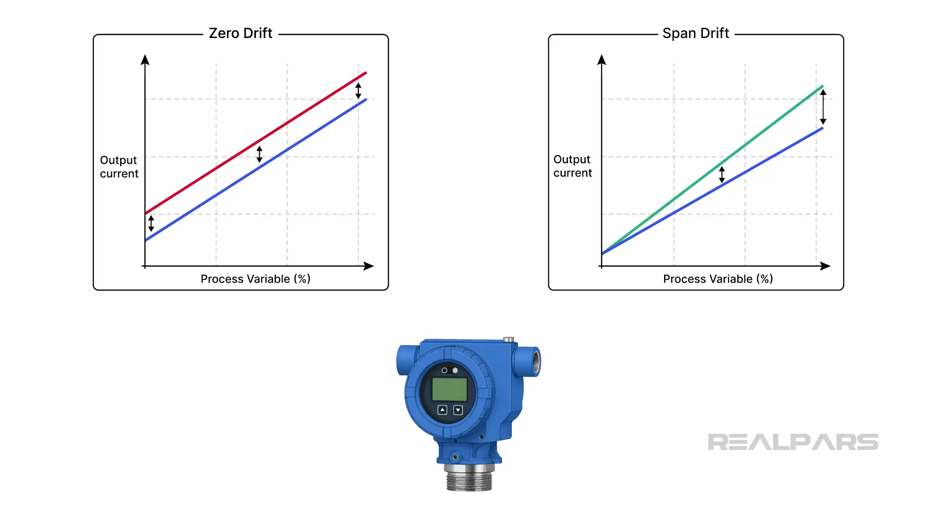
Zero Drift causes the entire measurement scale to shift by a fixed error. For example, in a 4 to 20 mA 2-wire loop, every measurement is shifted upward by exactly 0.32 mA. At a true 0% process variable, the transmitter sends 4.32 mA, and at 50%, it sends 12.32 mA. The error is 0.32 mA across the entire range.
With Span Drift, the measurement is accurate at the low end of the range, but the error increases as the process value rises.
For example, the measurement is accurate at a 0% process variable, with a transmitter producing an output of 4.0 mA. At 50%, the transmitter outputs 12.2 mA instead of 12.0 mA; at 75%, it outputs 16.3 mA instead of 16.0 mA; and at 100%, it outputs 20.4 mA instead of 20.0 mA.
Investigating the transmitter
Ok, let's go back to our storage tank, with a possible discrepancy of 4%. We’ll consider that is analog drift is the problem and seek the possible causes.
The primary level-measuring instrument is a differential pressure transmitter with the low side vented to the atmosphere.
The sensor may be damaged by its environment, causing the fragile capsule to warp over time. The transmitter may be worn and have degraded electronic components, as noted earlier.
Monitoring a live process variable proves nothing because you really don’t know what the true process value is. Therefore, we need to isolate the process from the sensor and connect an external pressure source, such as a hand pump, to simulate changes in level.
While measuring the transmitter loop current, apply a precise pressure input signal to simulate 0%, 50%, and 100% tank-level pressures to determine whether the transmitter exhibits zero drift, span drift, or both. Zero drift can often be corrected with a quick field adjustment, while span drift is often a more serious issue.
.webp)
Testing other process variables follows the same 'isolate and simulate' methodology. For example, use a precision resistance source, such as a process calibrator or decade box, to simulate temperature changes for an RTD sensor.
We’ve got a great article called What is an Instrument Calibrator if you are interested in learning more.
Investigating wiring and PLC hardware
Let’s move on to possible wiring issues.
Imagine the sensor-transmitter combination checks out within specifications in the field.
Moisture and corrosion are common causes of current loss when they occur in certain places. Water leaking into junction boxes or conduit runs can create unintended parallel-resistance leakage-current paths across your terminals or to ground. As a result, a portion of the loop current is drained away, bypassing the PLC input module. The PLC happily receives less current than the transmitter is actually producing.
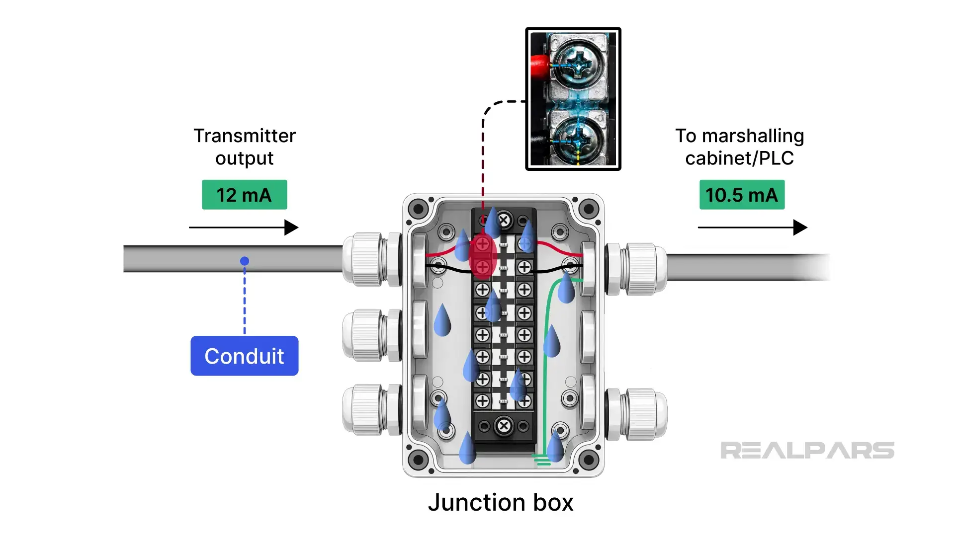
To verify this condition, measure the current in series at the marshalling panel, right before the PLC module, and compare it directly with a field current measurement.
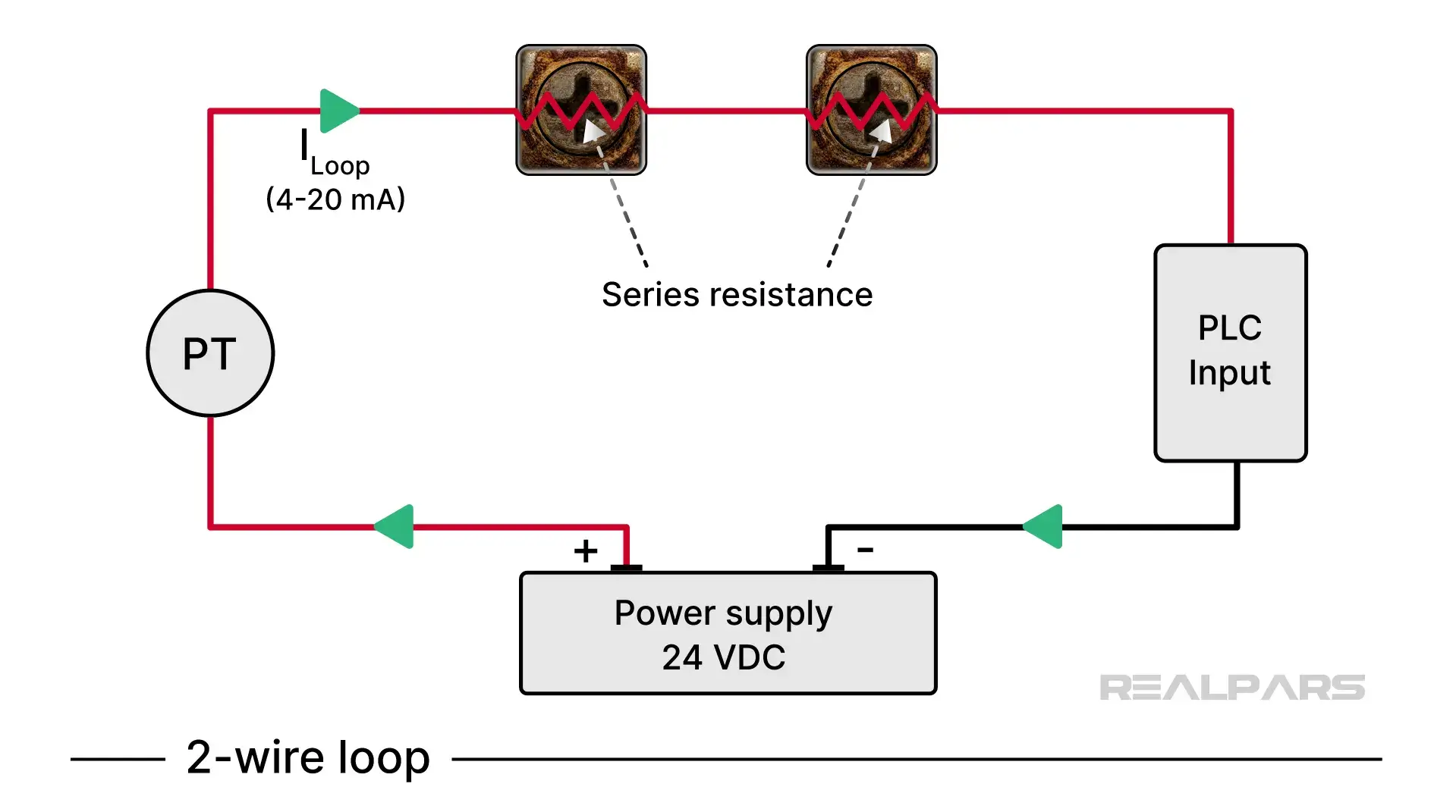
On a side note, terminal corrosion can introduce unwanted series resistance into the 2-wire loop. Interestingly, the transmitter compensates for this increase in loop resistance, keeping the loop current stable, so you might not notice the issue until it becomes catastrophic.
Okay, we’ve looked at the likely causes of analog drift. Let’s talk about some less likely possibilities.
PLC analog input modules include input circuitry that converts current to voltage before digitizing the signal.
Although input module drift is rare, it doesn’t hurt to understand the hardware design. The Allen-Bradley ControlLogix 1756-IF16 uses an internal 249-ohm precision resistor to convert 4–20 mA to 1-5 VDC.
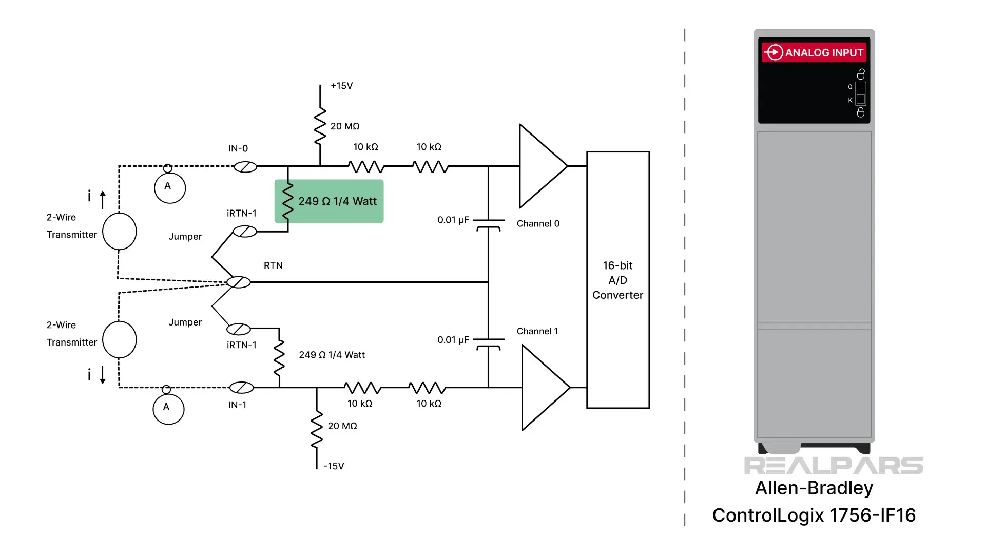
Why is a 249-ohm resistor used instead of a 250-ohm resistor? 249 ohms is a standard EIA 1% tolerance value, making it readily available off the shelf. When there are thousands of modules in production, why not use a standard resistor? It’s possible, though unlikely, that past electrical surges have degraded the resistor, permanently changing its resistance.
The Siemens Approach SIMATIC S7-1500 AI 8xU/I HF uses a low-impedance 25-ohm internal resistance, producing a small 0.5 V that feeds a high-gain internal pre-amplifier. Again, it’s highly unlikely, but that circuitry can be damaged by overvoltage or severe wiring faults.
Wrap-Up
The best approach to finding the culprit is the same as for any troubleshooting adventure. An experienced troubleshooter uses the "Half-split method" to divide and conquer the problem.
If the HMI shows a drifted value, split the loop at the marshalling panel.
Measure the current coming in from the field. If it's wrong, the issue is out in the field. If it's correct, the issue is inside the cabinet, possibly the marshalling terminals, safety barriers (if any), or the PLC analog module itself.
Here’s a tip for you. An experienced troubleshooter will tell you that if you don’t know what to expect, don’t take the measurement. If you don't know what the reading should be, you have no direction for what to do next.

