

An increasing number of industrial systems are replacing traditional analog signals with clean, noise-resistant pulse-width modulation.
Because the PWM output switches ON and OFF instead of maintaining a steady analog level, it results in lower power consumption and less heat production. We will explain the ON and OFF operations later in the article.
Pulse Width Modulation (PWM) sensors are now everywhere. In this article, we’ll explain in detail how a PWM sensor signal can represent a process variable, and show you how to test it with your trusty digital multimeter.
PWM sensors are used in various applications. For instance, they measure position and displacement, pressure and force, monitor speed and RPM, among other functions.
Analog and PWM sensors
Let’s start by identifying two analog sensors that are being replaced by PWM sensors.
Potentiometers
Potentiometers were once the preferred choice for many position measurement applications.
They were also common in joysticks, levers, and pedals.
Why are they being replaced by PWM devices? A potentiometer has a metal wiper that rubs against a resistive material to create a variable resistance. Over time, they get dirty and wear out. Cleaning them is nearly impossible, so they are often replaced.
However, they haven’t disappeared entirely and will likely be around for quite some time.
Shaft encoders
Alright, what about shaft encoders? Optical encoders have been used for decades to determine shaft position. There are PWM absolute encoders that offer better resistance to dust, oil, vibration, and shock; they do not rely on an LED light source and code disc to generate an output signal.
How PWM sensors work
Ok, now that we’ve discussed where you might find PWM sensors and why, let’s move on and explain how they work.
In simple terms, PWM involves adjusting the duty cycle of a constant-frequency digital waveform. With a PWM sensor, changes in duty cycle reflect variations in a physical parameter, such as rotation, position, or pressure.
Duty cycle and frequency
So, what is duty cycle? Let’s begin by discussing frequency.
In North America, we are all familiar with the 60 Hz frequency of an AC line voltage.
On an oscilloscope, the AC line voltage shows as a sine wave that repeats at 60 cycles per second.
Using simple math, we can determine that the time to complete one cycle, called the Period, is 16.67 milliseconds. How did we get that? The Period is the inverse of the frequency.
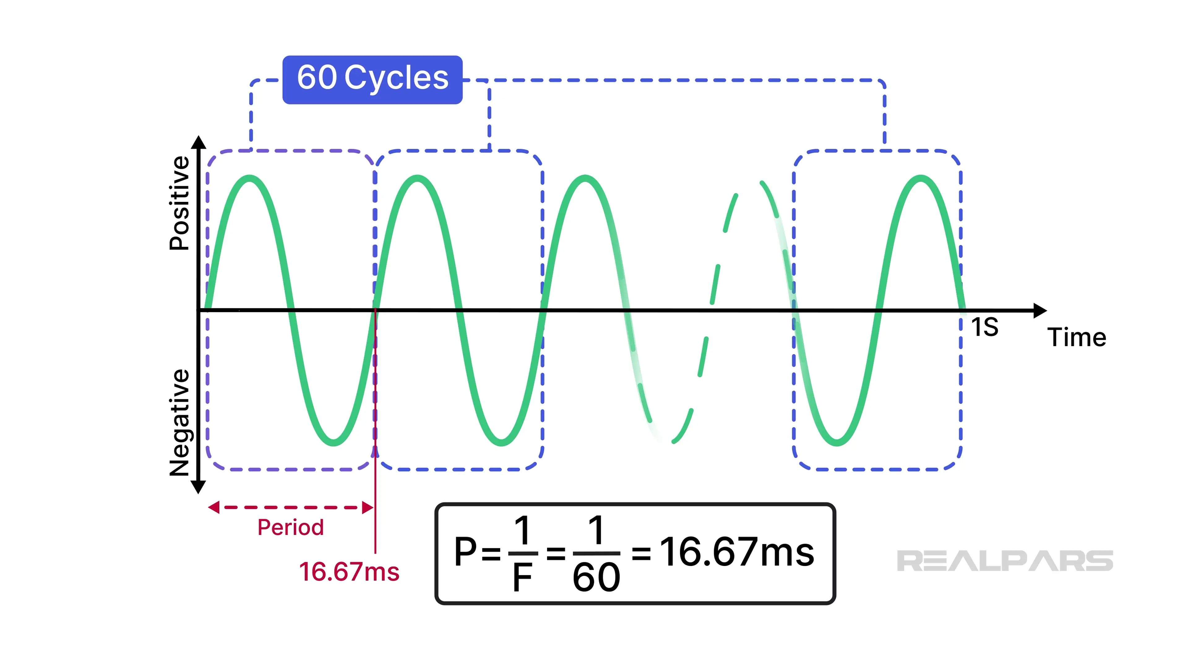
P is the period of one cycle.
Waveform types
Not all repeating waveforms are sinusoidal or alternate in polarity like line voltage. There are sawtooth waveforms and square waveforms, to name a few.
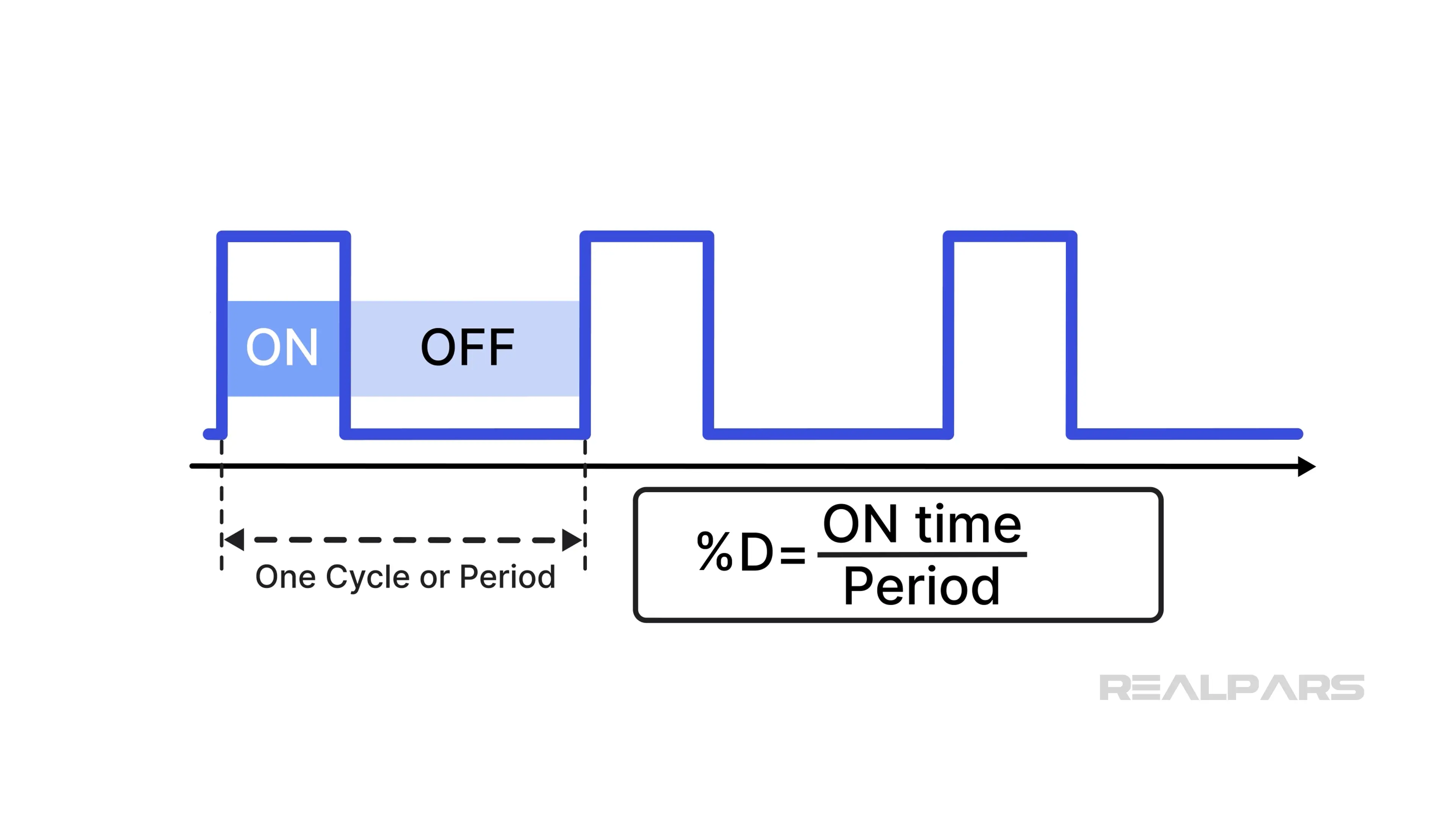
PWM is a repeating waveform where each half-cycle may vary in duration.
Each cycle of the waveform has a time when the voltage is ON and another when it is OFF.
Duty cycle is the proportion of ON time to the period, or the duration of one cycle. Duty cycle is expressed as a percentage.
PWM sensor example
Let’s look at an example.
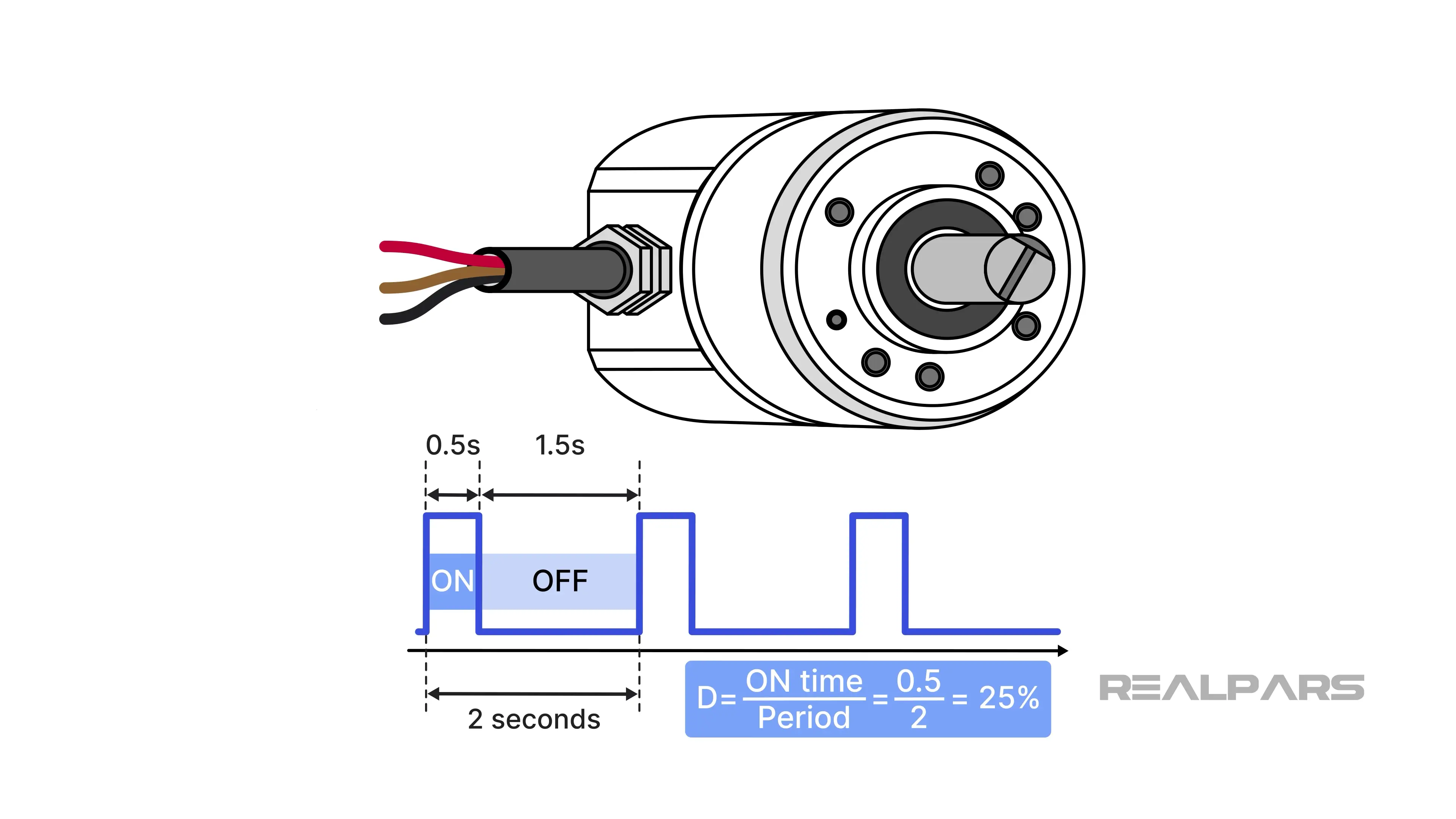
We have a PWM sensor with a period of 2 seconds and an ON time of 0.5 seconds. The duty cycle is the ratio of the ON time to the total period. In this example, that’s 0.5 seconds divided by 2 seconds. Remember, we express the duty cycle as a percentage, so it is 25%.
The Megatron HTP36 series device is a single-turn Absolute Encoder with a PWM output.
It operates at a frequency of 244 Hz. The duty cycle ranges from 10% to 90%, which corresponds to a rotation of 0 to 360 degrees. With a supply voltage of 5V DC, we can assume the ON time voltage pulse is 5V DC.
Why does the duty cycle vary from 10% to 90%? This range is common for PWM sensors, although 5% to 95% is also typical. The full 0% to 100% range is not used for diagnostic purposes. A signal below 10% or above 90% indicates a potential fault condition.
Observing a PWM signal with an oscilloscope
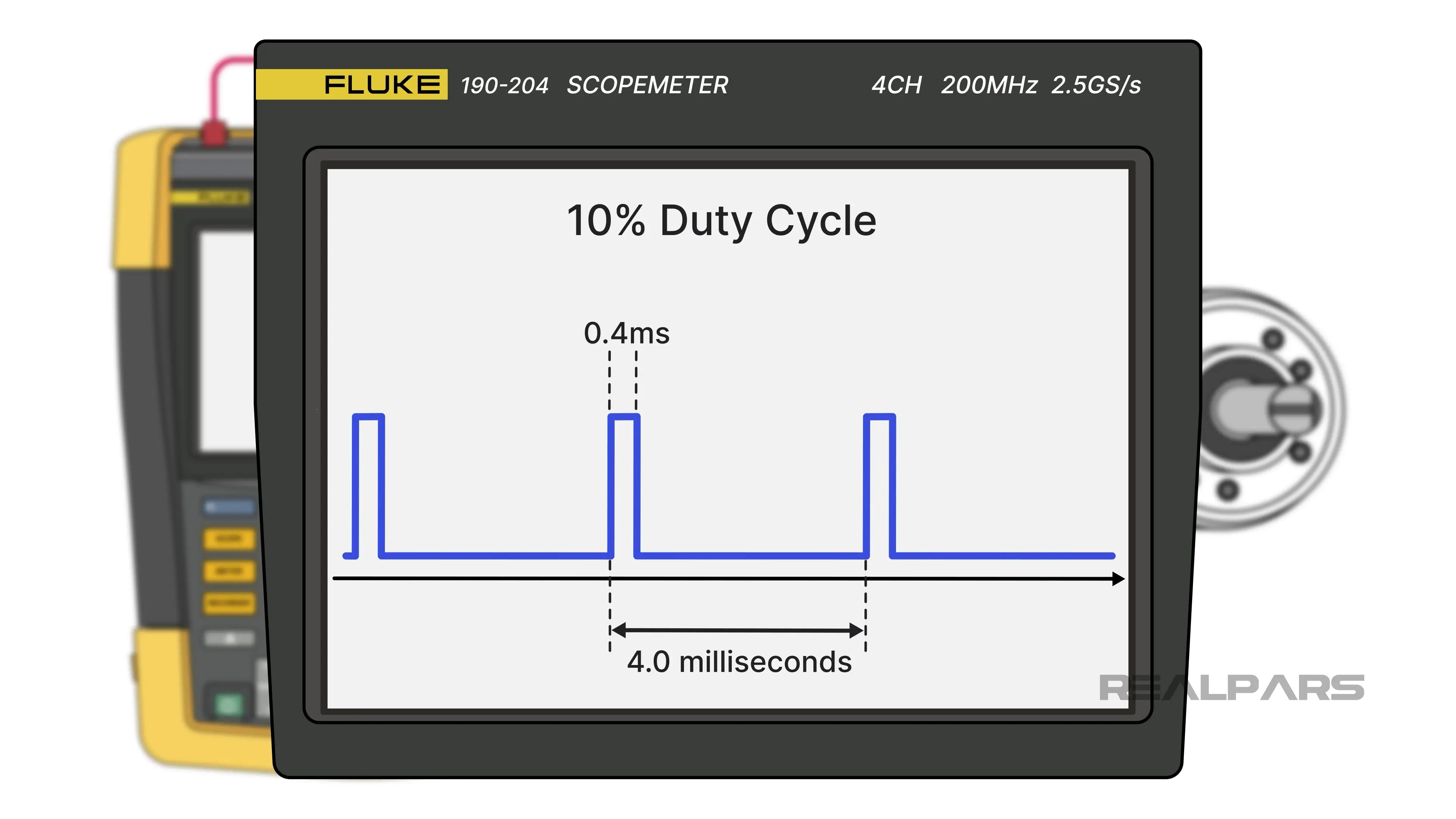
Let’s examine the waveform we would observe on a Fluke 190 portable, battery-powered oscilloscope connected to the output of this encoder.
At a 0-degree rotation, we observe a 10% duty cycle. The waveform period is 4.0 milliseconds, and the ON time is 0.4 milliseconds.
At a rotation of 360 degrees, we observe a 90% duty cycle. As usual, the waveform period is 4.0 milliseconds. The ON time is 3.6 milliseconds.
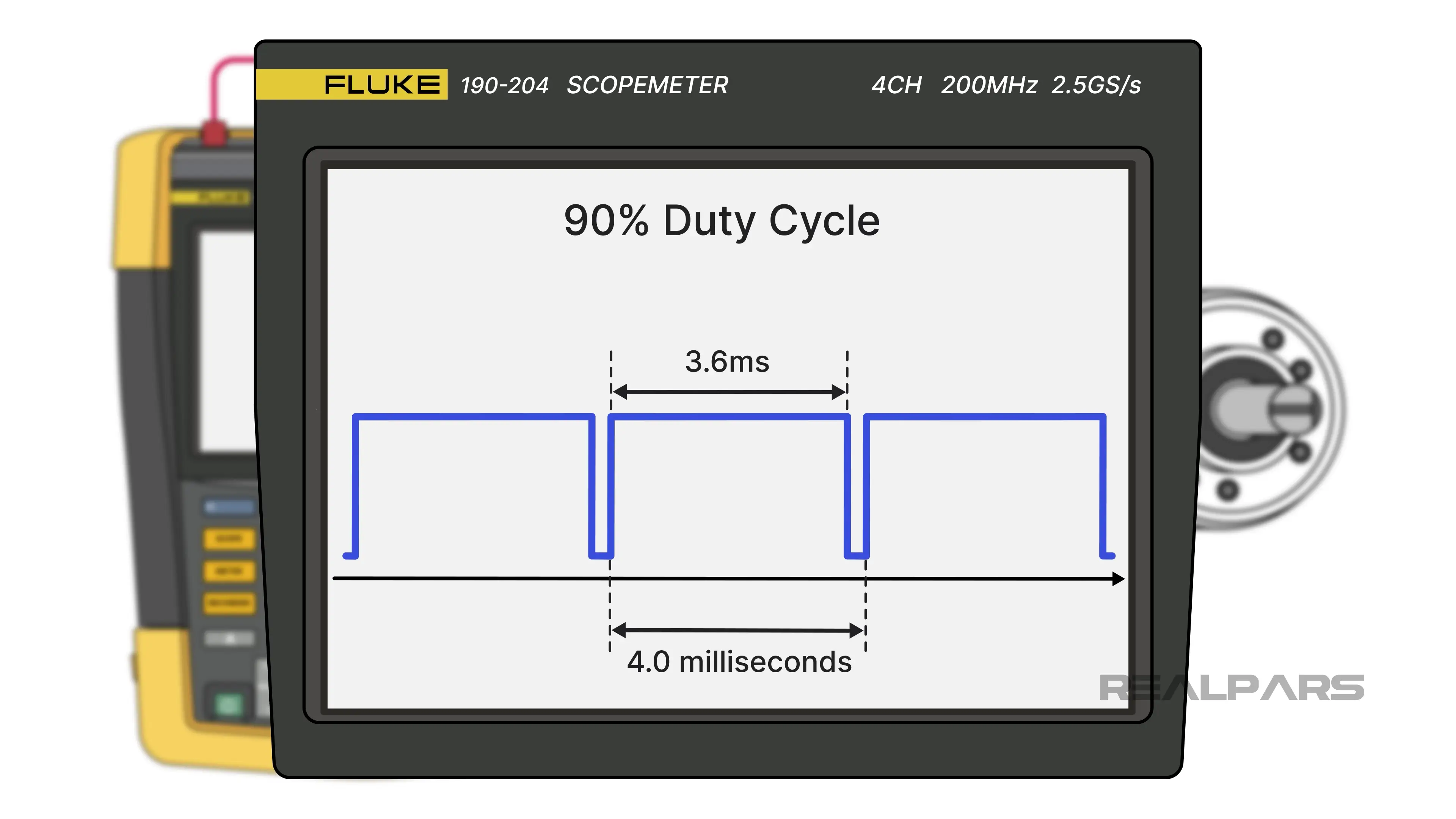
It’s worth noting here that the specification states a maximum duty cycle of 90%, which is roughly 3.5 ms.
Why the difference? Essentially, this is standard practice on data sheets. The manufacturer rounds values for simplicity.
Measuring PWM signals with a digital multimeter
Well, it’s great if you or your company can afford an expensive portable oscilloscope, but not many can.
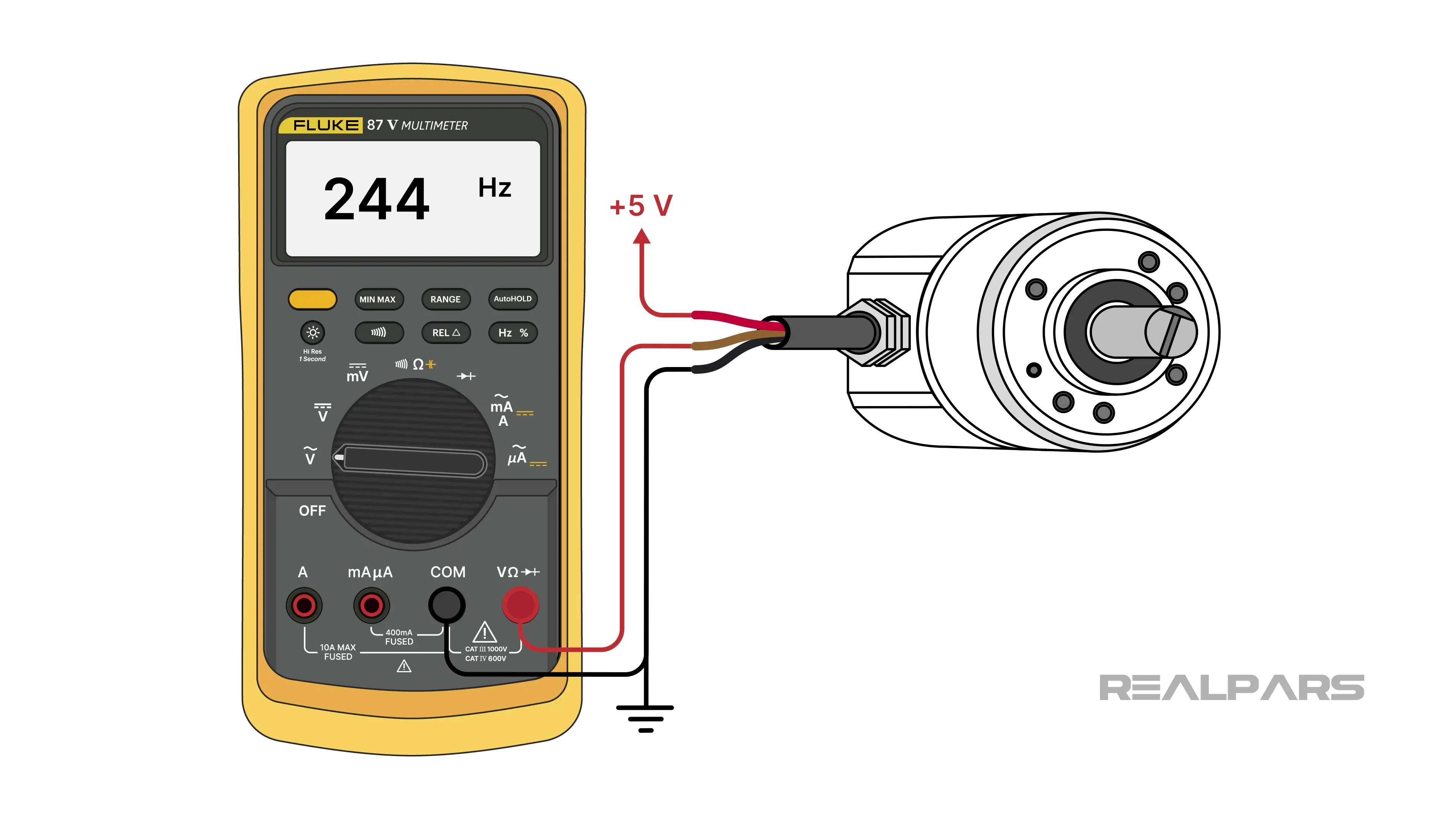
All you really need is a DMM (digital multimeter) with a couple of special options, like the Fluke 87V, that can measure frequency and duty cycle.
A PWM sensor is an active device, unlike a potentiometer, which is passive. It needs power to operate. There are no ohmmeter tests you can perform to determine if it is serviceable.
This particular DMM has a button labelled Hz with a % percentage sign.
This button lets you measure frequency in hertz and duty cycle as a percentage with a single push.
To measure frequency, connect the leads to the VAC DMM terminals and set the selector to AC volts. Connect the leads as you did with the oscilloscope. Press the Hz button once, and the display will show the frequency in hertz.
Remember, the PWM frequency remains constant; therefore, the reading should not change when rotating the encoder.
To measure the duty cycle, keep the same leads attached. Press the Hz button again, and the display will now show the duty cycle as a percentage. You will see the duty cycle value change from 10% to 90% as you rotate the encoder from 0 to 360 degrees.

It will be obvious whether the sensor is dead, questionable, or unstable from the DMM readings.
Testing PWM sensors using DC voltage
If your DMM does not have the option to measure frequency or duty cycle, all is not lost. You can still get a rough idea of a PWM sensor’s operation by setting the meter to measure DC volts. In this mode, the DMM shows the average of the pulsed waveform.
As the duty cycle varies with encoder rotation, the average DC voltage also changes. When the duty cycle increases, the measured DC voltage rises accordingly.
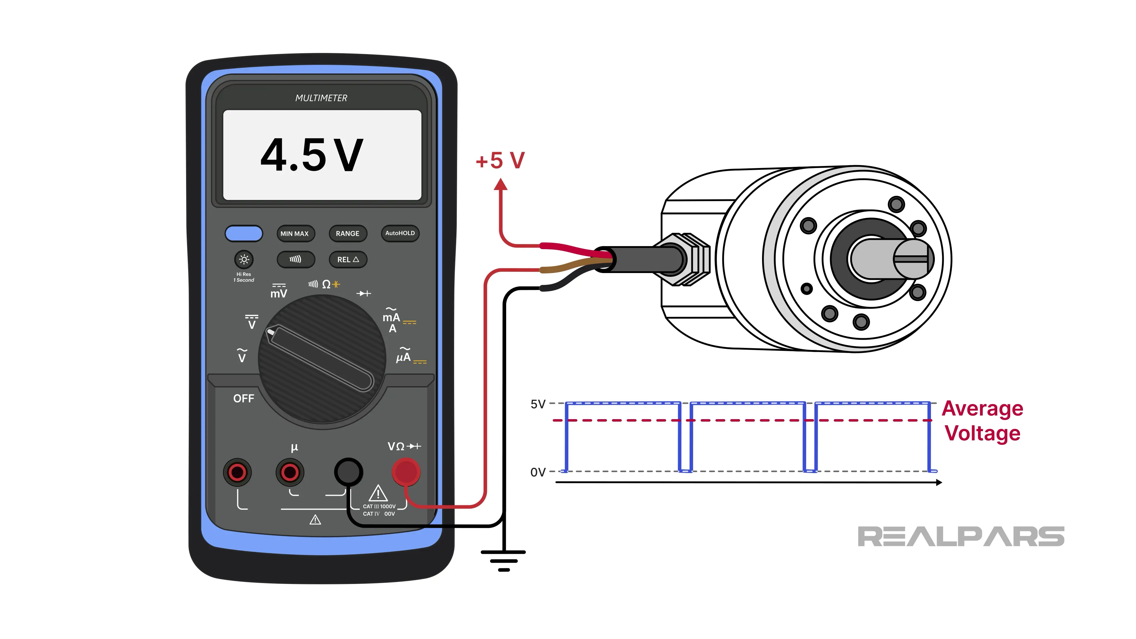
You will not be able to determine the duty cycle with this method. However, if the DC voltage remains unchanged as the encoder rotates, the PWM sensor should be considered suspect.