
In this article, we will discuss what a PLC, or Programmable Logic Controller is. We’ll discuss its historical developments from computer engineering that made industrial controls advance.
We will show that a PLC is a computer that has been adapted for industrial environments. We will talk about the advantages of PLCs over traditional relay logic.
This article will touch on programming the PLC. Lastly, the article will cover the knowledge and skills needed to program and maintain PLCs.
What is a PLC?
The PLC is a computer that has been adapted for industrial use. What does that mean? PLC controllers and components are selected to meet heat and vibration standards set for industrial environments.
PLC operating systems also do not have the same overhead as Windows or Apple machines.
Regular computers can be configured for PLC-type processing but are not considered reliable for industrial control.
Thus, picture a box with smart relays and a user interface.
PLC vs PC is talked about in RealPars article PLC vs. PC but we can briefly describe the similarities and differences here.
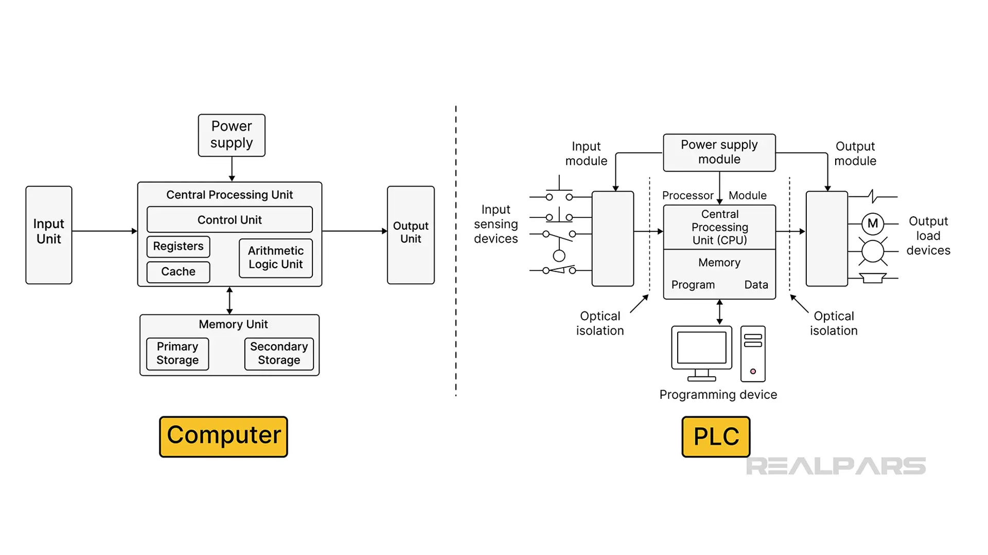
For instance, the main components between a PLC and a computer are the same.
A PLC has inputs, outputs, and a central processing unit or CPU. The CPU is programmed via an interface that allows a human-created program to be converted into machine language understood by the CPU. This machine language is stored in memory as 1’s and 0’s.
The program is downloaded from a computer once it is compiled and has no errors. The PLC will be put into run mode to run the program.
The PLC can then use the program to make decisions about the condition of the inputs to turn on or off outputs. This is the basis of the PLC.
It is also the way that a computer application works. You should be able to see similarities when comparing the architecture of the PLC and a computer.
The two architectures are the same. If you compare the architectures side by side, there are inputs, outputs, power supply, CPU, memory, and buses to interconnect. There is also a user interface for each.
The ability to program memory locations in a computer allowed a virtual digital representation of a physical relay. This enabled automobile manufacturers in the sixties to create assembly lines faster, with less labor. This efficiency led to PLCs being implemented over relay systems.
Why did PLCs replace relays?
Hardware-wise, the relay system that was used previously is now virtually inside the PLC. The decision-making relays are replaced by virtual relays and logic symbols.
Historically, ladder diagrams mimicked the wiring of relay systems, but if you understand Boolean logic, it does not matter if you are physically wiring relays or programming a PLC, you can understand what has to be done, to make outputs come on and for a machine to change states.
Let’s Look at how a ladder relates to a wired relay circuit.
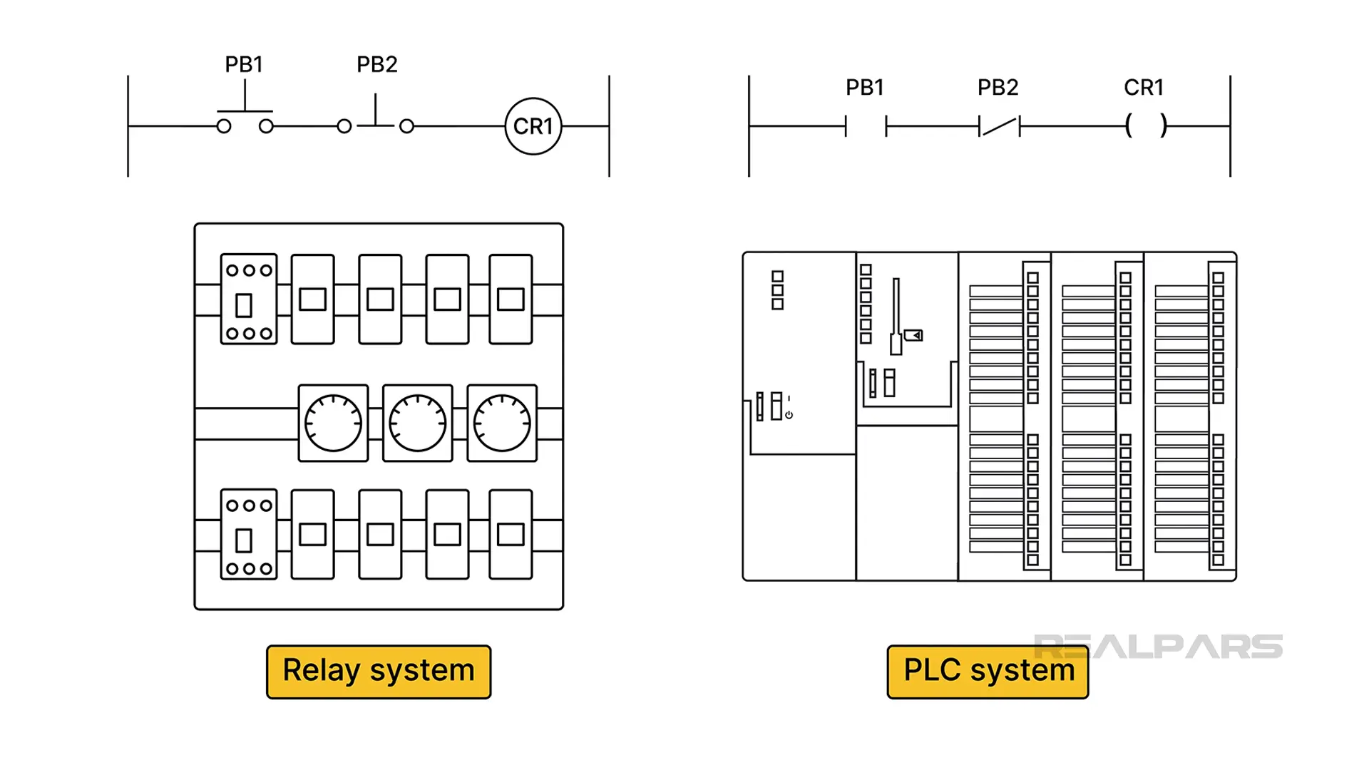
Note in the comparison diagrams that the system using a PLC has much less wiring. If it still is not clear, think about how human machine interfaces (HMIs) reduce wiring today. It’s the same idea.
Relay Diagram to Ladder Diagram
Relay diagrams are like ladder logic in a PLC software development environment. Some of the symbology is different but the outcome is the same.
Inputs, turn on a coil, or output.
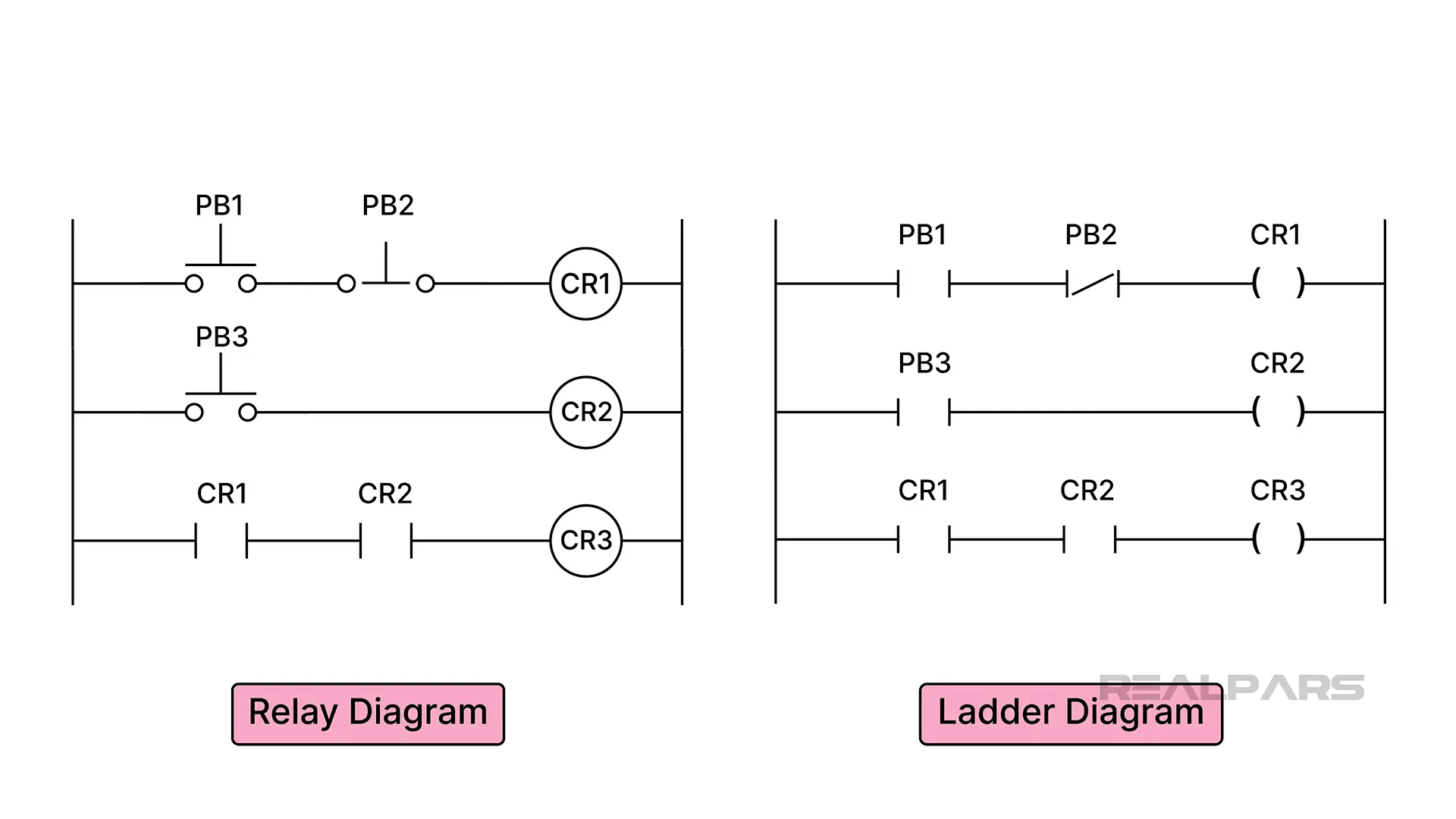
Let’s convert a traditional relay diagram to a ladder logic diagram and finally to the Boolean logic representation of each.
A relay diagram is used to show electricians how to wire relays.
A PLC programmer may use it to make a logic program.
Boolean Logic can represent either the physical relay circuit, or the PLC ladder logic digital representation. Boolean logic is a way of describing a binary format that applies to building a relay system or a program.
Oddly enough, the same Boolean logic applies to programming computer chips.
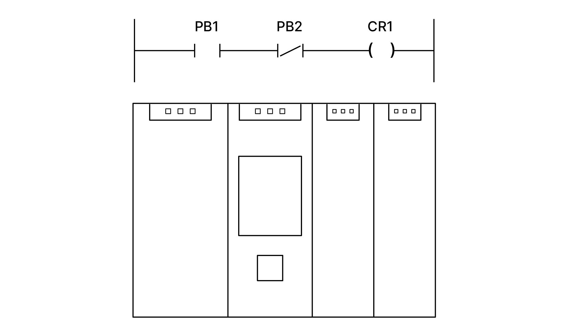
You can also represent the logic in a table format. Coil 1 or CR1 is turned on when push button one (PB1) is pushed and push button two (PB2) is left alone.
PB1 is normally open and PB2 is normally closed. Think about it this way: If PB1 is a start button and PB2 is a stop button, then you would push PB1 to start and push PB2 to stop.
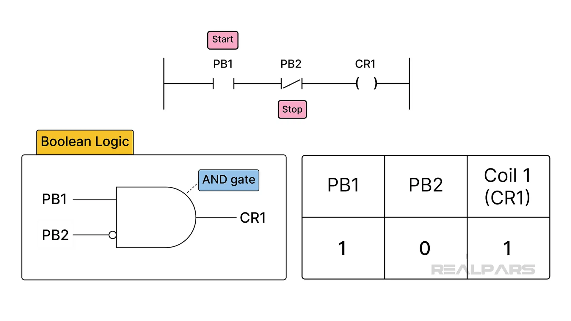
The point of the table is to understand the pattern. This will allow you to use and troubleshoot whatever kind of language a PLC is programmed in.
The International Electrotechnical Commission (IEC) recognizes five PLC languages:
- Ladder Diagram,
- Function Block Diagram,
- Structured Text,
- Instruction List,
- And Sequential Function Charts.
Once all of the logic is worked out via line drawings or tables or ladder diagrams, then a program can be made and downloaded into the PLC and it becomes an application. This is usually via Ethernet or USB connections.
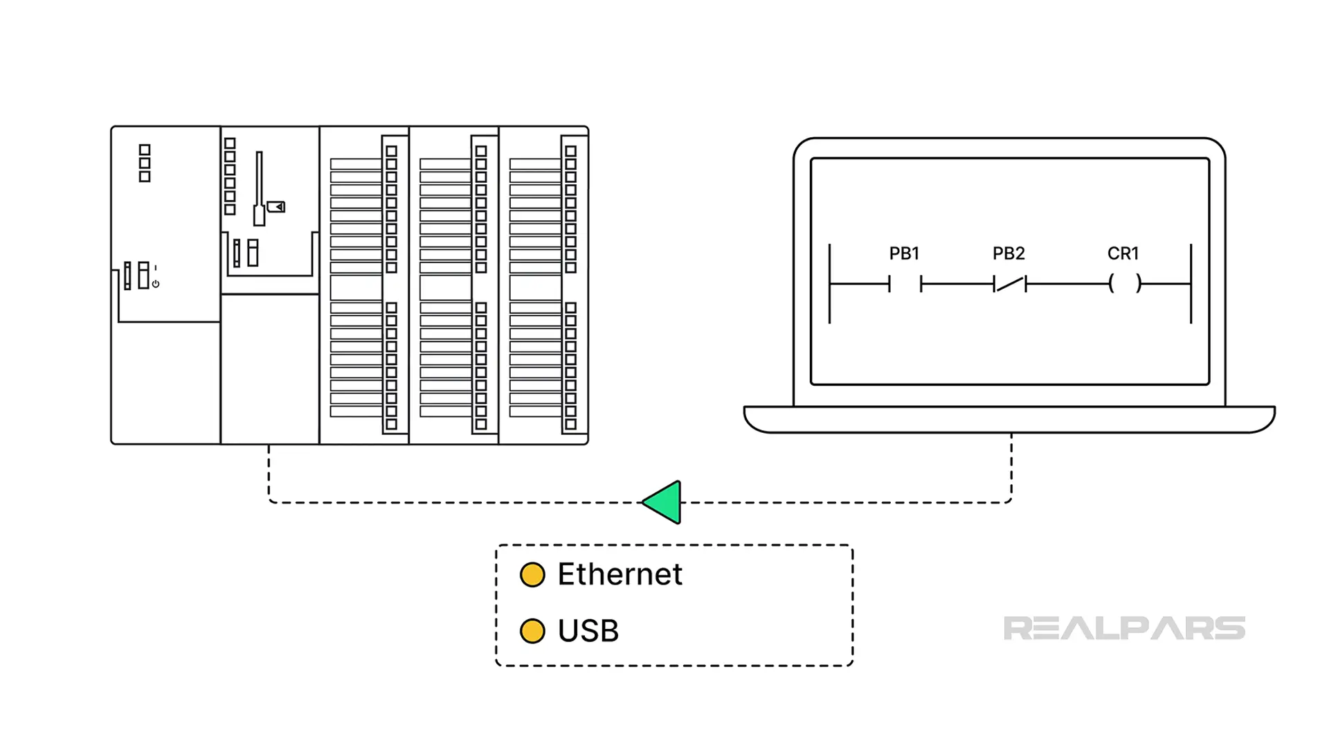
Previously, it might have been data highway or serial connections. This is how the relays get digitized, so to speak. Why is it possible? Advancements in computer engineering.
Evolution of PLC technology
The computer was developed in 1942. The Atanasoff Berry Computer or ABC used vacuum tubes and took up a large amount of space.
Transistors were derived in 1947.
The first monolithic chip was made in 1959, by Robert Noyce.
The first PLC followed. Dick Morley created the MODICON 084 for General Motors in 1968. MODICON is short for Modular Digital Controller.
Other advancements that made PLCs possible and advanced industrial communications and signal processing are digital excitation controllers (DEC) and the ability to convert analog to digital and digital to analog at the chip level. Pulse code modulation (PCM) allowed analog signals to be put into a binary form.
The Rockwell Allen-Bradley PLC platform has also gone from a larger footprint to a smaller footprint.
This coincides with the advancement of computer engineering and changes in chip technology.
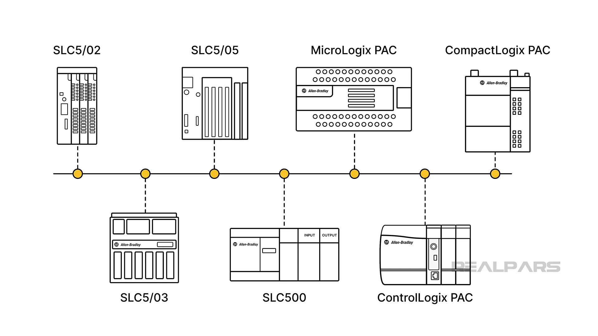
If you want to know more about Rockwell PLCs' development, check out Introduction to Allen Bradley and Evolution of Rockwell PACs.
Skills needed to program a PLC
Control systems engineers, programmers, and technicians need to have mechanical and electrical knowledge. The ability to read schematics and understand processes is also necessary because this must be put into logic for the PLC to achieve the desired states needed to run a process.
Computer programming skills, problem solving, and attention to detail are required. In addition, hardware and software knowledge related to the control software environments provided by Rockwell, Siemens, Schneider, CODESYS, and the like, is required.
Learning PLCs allows you to be able to automate ideas and make processes better. Understanding how the PLC plays a role in operations and how to use it as a tool is key.
Conclusion
The PLC is a computer. It can be basic. It may fit in your hand.
It can be complex. A complex PLC-based system may have many racks.
It may provide motion control or determine temperatures by reading thermocouples but at its base, it's still a computer. Thus, it can withstand industrial environments.
At its core, it's still just a computer, converting human interpretation and signals to a binary format, deciding, and turning on an output like a relay system. It is just doing it digitally.
If you are interested in learning PLC programming, several courses, such as the PLC Programming Made Easy and CODESYS course series, can help you.