

Magnetic flow sensors are a very commonly used flow meter type that is useful in a wide range of applications and line sizes.
Accurate and repeatable measurement of flow is a requirement for industrial processes, including feed streams, tank recirculation loops, product transfer lines, and many others.
In this article, we will:
– Introduce you to the working principles of a magnetic flow sensor,
– Describe the physical characteristics of a magnetic flow sensor that make it valuable for process control,
– Describe the ways magnetic flow sensors can be integrated into a measurement and control system.
What is a magnetic flow sensor?
Magnetic flow sensors convert the velocity of a flowing fluid into a measurable electrical signal that is proportional to the flow rate.
Magnetic flowmeters have no moving parts or internal flow path obstructions, so they are easy to calibrate and maintain.
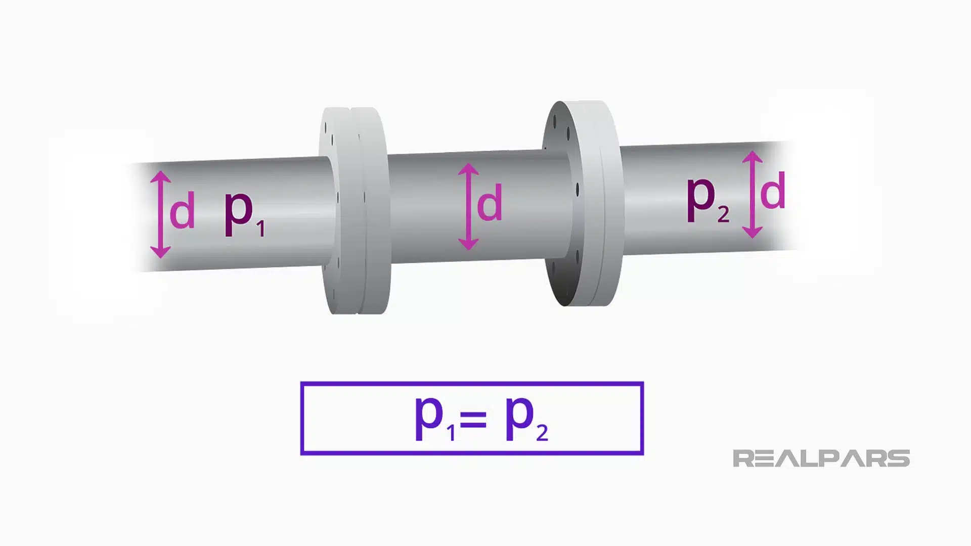
Because magnetic flow meters are typically specified to be the same size as the upstream and downstream piping, there is virtually no pressure loss through the flow meter, which can be very advantageous for some flow streams, like thick slurries.
So let’s take a look at these properties and characteristics of magnetic flow meters. We will explain how they work, when to use them, and what needs to be specified to select the proper sensor for your application.
Magnetic Flow sensors are often called mag meters, and we will refer to them using this abbreviation.
The magic is in the magnet
Let’s look at the physical properties of how a Magnetic Flowmeter converts velocity into a flow signal that can be used in a control system.
Previously, we mentioned that mag meters convert a velocity into a measurable electrical signal. How does this happen?
Mag meters are typically full-bore sensors, meaning that the internal flow path is of the same diameter as the upstream and downstream connections.
This construction eliminates any restriction of the fluid which may alter the flow path or create a pressure drop.
Fluid passes through the mag meter in a straight line through the bore of the sensor. This regular, cylindrical geometry also allows a constant and directional magnetic field to be established across the diameter of the flow path.
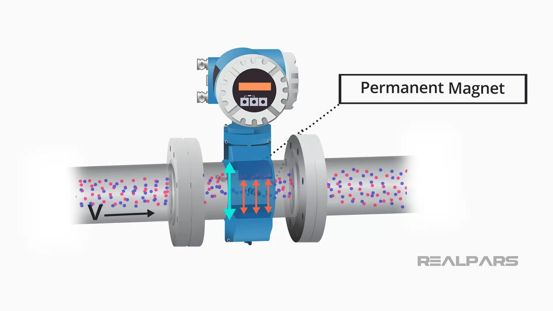
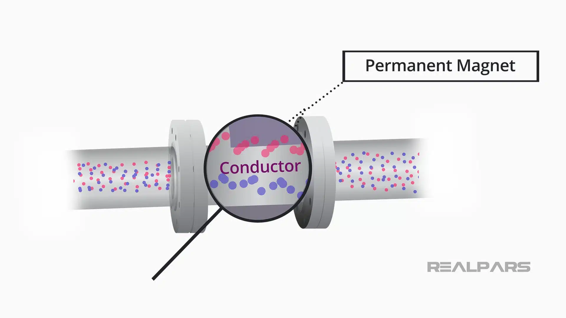
The magic that creates the flow signal is based in the magnet! The mag meter is surrounded by an iron-core, permanent magnet that creates a magnetic field to be established with lines of magnetic flux which pass vertically through the entire cross-section of the pipe and the flowing fluid.
This geometry is very important. The flowing fluid will pass through these lines of magnetic flux at a 90-degree angle or perpendicular to the lines of magnetic flux.
Faraday’s law
In 1831, Michael Faraday observed that a voltage is induced across any conductor as it moves at right angles through a magnetic field and that the voltage is proportional to the velocity of that conductor. This is called Faraday’s Law of Electromagnetic Induction.
To generate a voltage according to Faraday’s law, we must have a moving conductor.
What is the conductor in our flow application?
We had mentioned that our mag meter has a stationary, permanent magnet, so the conductor must be the flowing fluid! And, indeed, it is!
And as the flowing fluid passes through the magnetic field at right angles, according to Faraday’s Law, a voltage must be developed that is proportional to the fluid velocity.
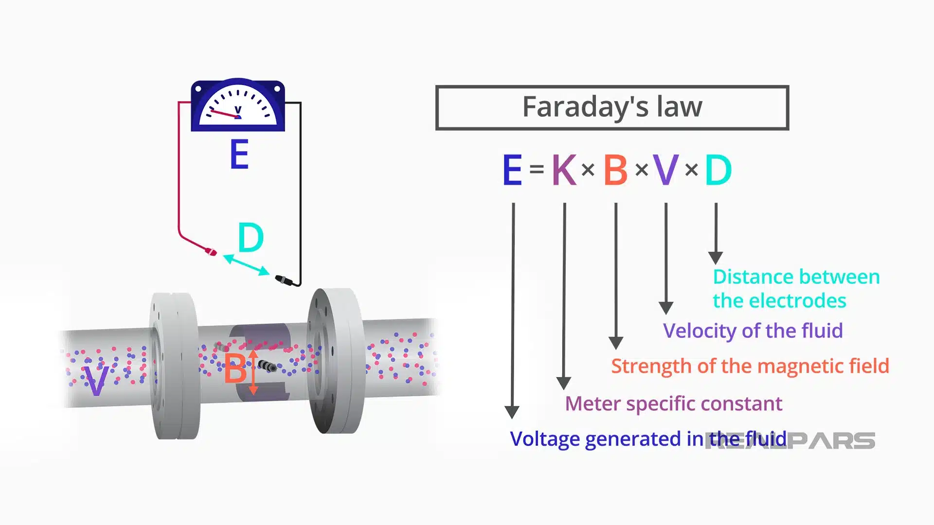
Faraday’s Law can be expressed simply as E is proportional to k × B × V × D, where:
– E is The voltage generated in the fluid,
– k is The meter-specific constant,
– B is The strength of the magnetic field,
– V is The velocity of the fluid,
– D is The distance between the mag meter’s electrodes.
Signal transmission
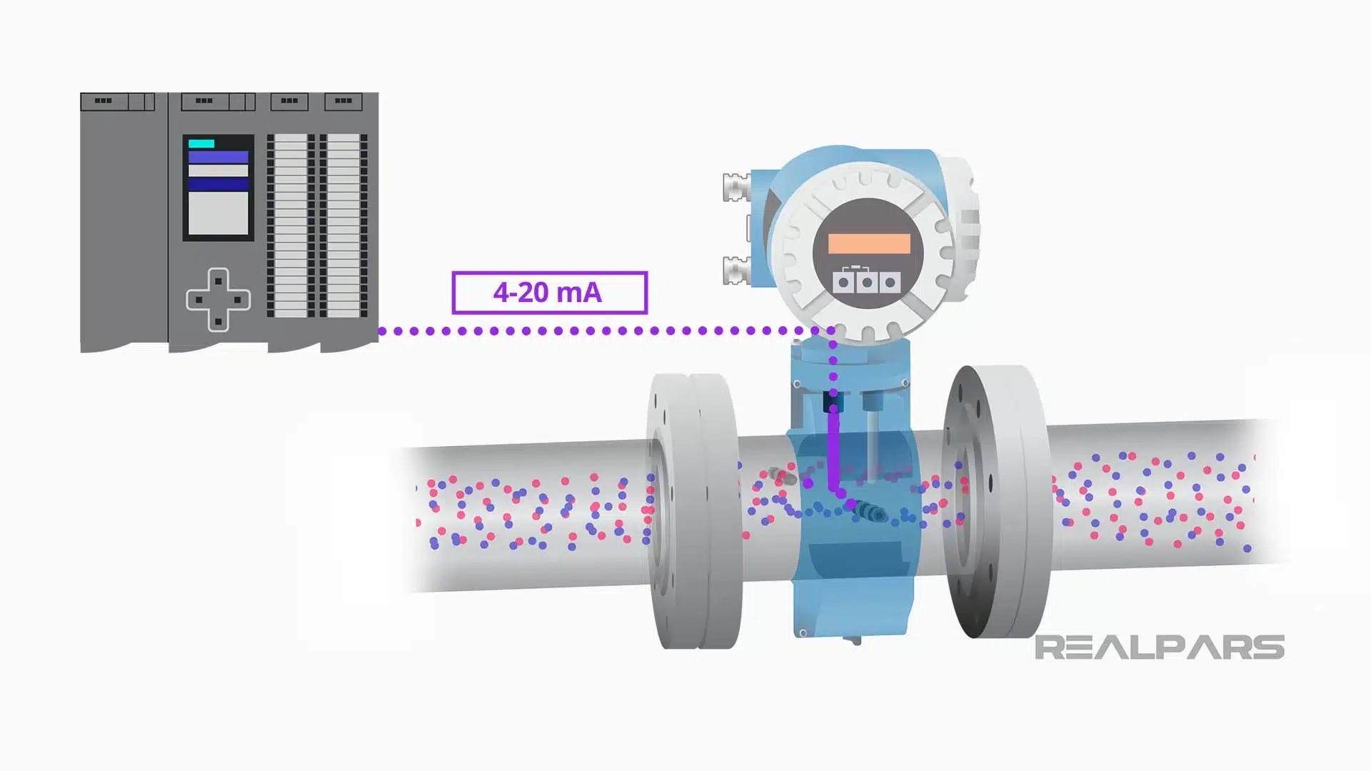
The generated EMF or electrical potential, or voltage, is sensed by two leads, or electrodes, which are connected to the mag meter’s transmitter.
The transmitter translates the strength of this electrical signal into a volumetric flow rate and sets the transmitter’s 4 to 20 milliamp output to provide an analog signal to the control system.
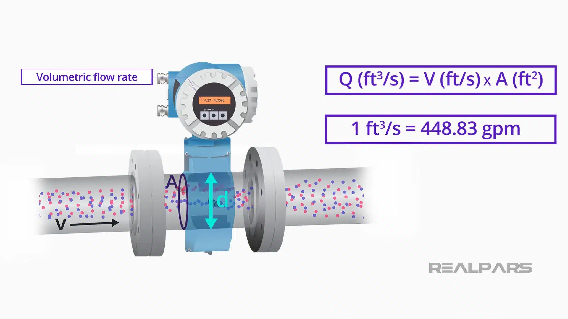
The transmitter outputs a volumetric flow rate. The meter measures the flow velocity.
The cross-section diameter, and hence cross-sectional area, is constant, so the resulting measured value of velocity in feet per second multiplied by the constant area in square feet, gives a volumetric flow rate ate of cubic feet per second.
This quantity can be scaled to any volumetric flow unit such as gallons per minute.
Conductive fluids
But there is one key parameter that cannot be overlooked that we mentioned previously. We must have a moving conductor to generate the required electrical signal.
We said the flowing fluid was the conductor, so the fluid must be conductive to work with a magnetic flowmeter.
What does it mean for a fluid to be conductive? It means that the fluid must be able to conduct an electrical charge, thereby establishing a voltage that can be sensed by the mag meter’s electrodes.
The conductivity of liquids is measured in units of micro-Siemens-per-centimeter. Some fluids, such as seawater, have high conductivity, and seawater flow can be measured with a mag meter.
Distilled water, on the other hand, has a very low conductivity, and cannot be measured with a mag meter.
Flow rates of vegetable and other oils, hydrocarbons, and most organic solutions cannot be measured with a mag meter.
In addition to seawater, flows of wastewater, and ionic solutions such as acids can easily be measured by magnetic flowmeters.
Fluids should have a conductivity of greater than 10 micro-Siemens-per-centimeter to be assured of good flow measurements with a mag meter.
Other considerations for installation
In addition to being able to measure a wide range of fluids, in-line magnetic flowmeters can be lined with Teflon or other materials to stand up to corrosive or erosive fluids, like slurries and acids.
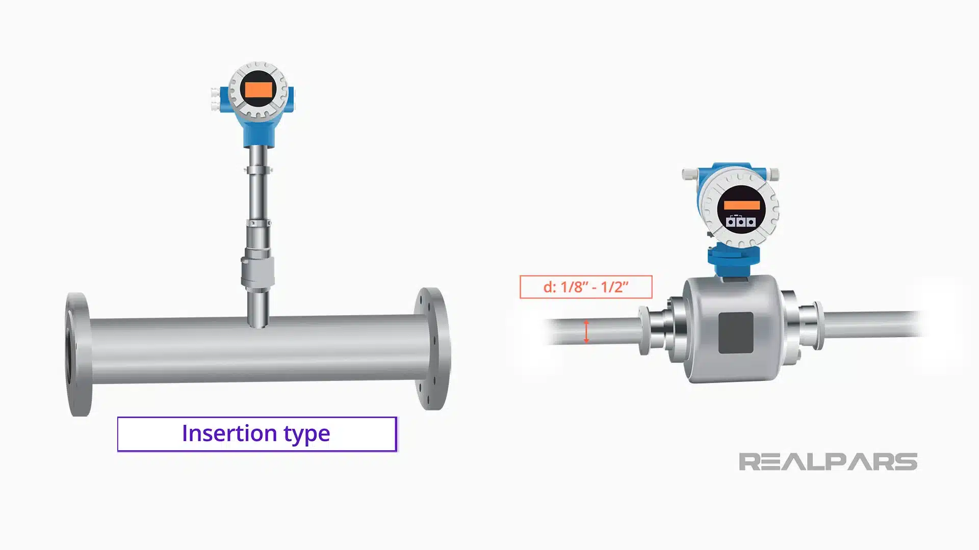
Types of magnetic flowmeters
There are other types of magnetic flowmeters that can be used, including insertion type, typically used with larger pipe sizes, and low-flow magnetic flowmeters, which are typically ⅛ inch to ½ inch in diameter.
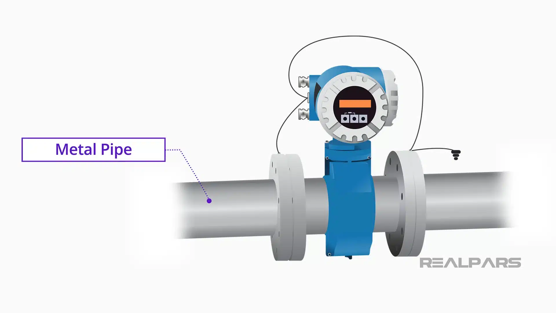
Magnetic flow meter grounding
When installing a magnetic flow meter in process piping, it is vitally important to follow the manufacturer’s recommendation for grounding.
The electrical signal produced in a mag meter is a very small DC voltage, and stray voltages along a pipe due to welding equipment or other large electrical loads in the plant.
For conductive metal pipes, the outside flanges and transmitter casing should be bonded and grounded.
For plastic or other non-conductive piping, manufacturer-recommended grounding rings should be installed to prevent stray voltages.
Grounding rings are also recommended for fluids with low conductivity, less than 100 micro-Siemens-per-centimeter.
Magnetic flow meter Transmitter
Transmitters are always used with mag meters. They convert the small DC voltages generated by the flowing fluid into signals that can be connected to the control system.
The following transmitter outputs are available:
– 4 to 20 milliamps
– Foundation Fieldbus
– IO-Link
Magnetic flow meter specification
When specifying magnetic flowmeters, some important aspects must be considered in addition to the conductivity of the fluid and the need for grounding rings.
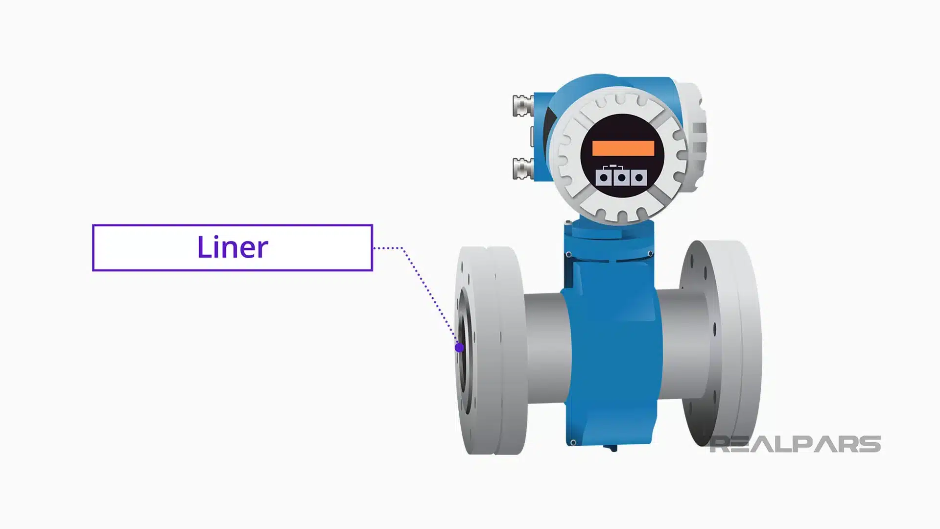
If the fluid is corrosive or abrasive, a compatible liner should be specified. These liners can also be replaced if they become worn, and they do not affect the measurement accuracy.
Knowing the minimum and maximum flow rates for your process can help determine the range of flow a specific mag meter model will be able to measure.
Each model has a low-flow cutout point and a maximum velocity that can be measured accurately.
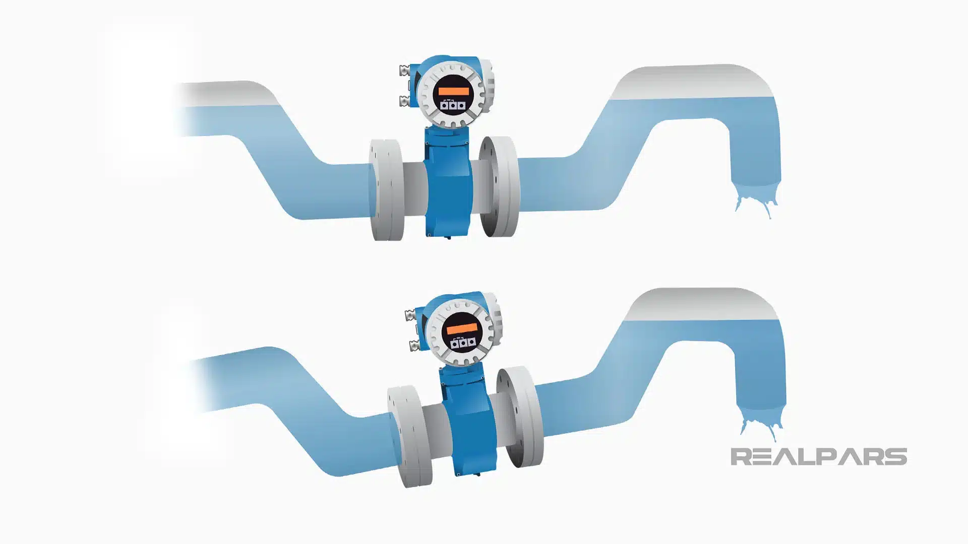
If the pipe will not always be full of fluid, flow accuracy will be affected. It might indicate the meter needs to be installed at a low point in the pipe or in an upwardly sloped pipe run to ensure a complete fill during operating conditions.
Summary
In this article, we introduced you to the working principles of the magnetic flow sensor, its physical properties, and how mag meters are used in industrial measurement and control systems.
We demonstrated the linear relationship between the velocity of the flowing fluid and the electrical signal developed based on Faraday’s Law.
Using proper grounding techniques, selecting the best location for installation, and understanding the minimum and maximum flow limits for the meter will help ensure accurate flow measurement.
So the next time you see a magnetic flow meter installed in a plant, you will have a much better understanding of how this simple, yet sophisticated sensor measures flow.