
As an automation professional, you may require monitoring, controlling or testing using real-time manufacturing or process plant data from an Excel spreadsheet. This data could be helpful also to your management, research and other department personnel requiring real-time data for decision making. With this and the previous lesson, we’ll show you how to achieve this and more using Microsoft Excel and communication called Dynamic Data Exchange (DDE) and Visual Basic for Applications (VBA).
Which Software Will be Used?
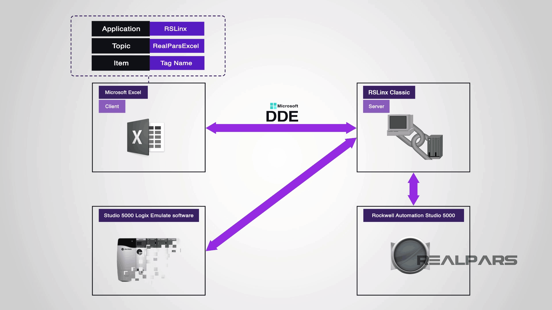
We will use Microsoft Excel to write data to Rockwell Automation Studio 5000, using RSLinx Classic and Studio 5000 Logix Emulate software.
The Studio 5000 Logix Emulate will communicate with RSLinx Classic and in turn, RSLinx will communicate with Studio 5000 Logix Designer and Microsoft Excel.
The overall block diagram of how the programs are interconnected is displayed below.
What is DDE?
let’s recap on what is DDE? DDE is a Windows mechanism that enables applications to communicate with each other. A DDE communication is known as a conversation between Client, which initiates the conversation, and Server, which responses to the request.
To initiate a DDE conversation, a client specifies the three items:
The Application, the name of the application it wants to talk to. Usually, this is the application executable’s filename, for example, RSLinx.
The Topic, the subject of the conversation created by the user and should be something which makes sense, for example, RealParsExcel.
And the Item; Any number of different Items may be referred to identify data to be passed between the applications, for example, Excel recognizes cell references as items and RSLinx recognizes program tag names as items.
Studio 5000 Logix Designer
Logix Designer Sample Program
So, let us begin with the previous sample PLC program. We’ve created a Studio 5000 Logix Designer program called RealPars_Excel.
REAL and DINT arrays
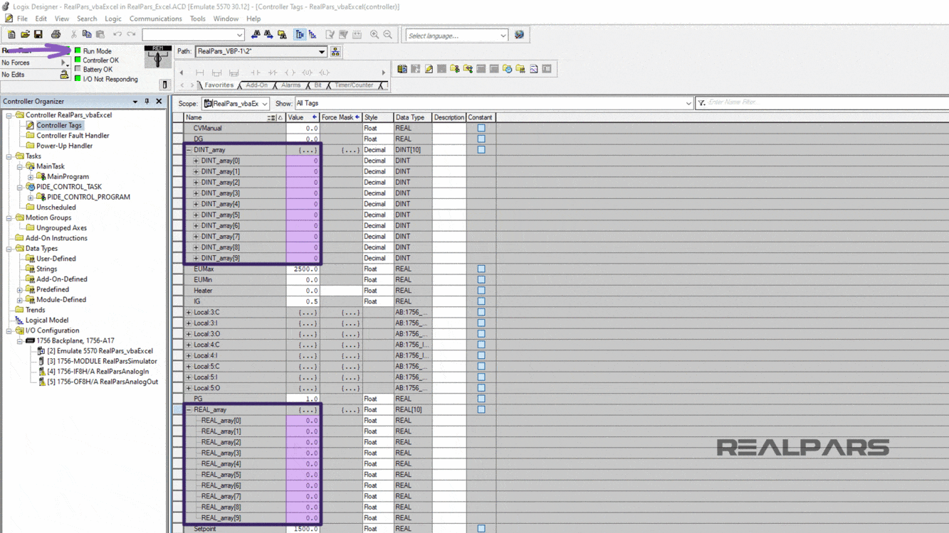
In the previous article, we opened the Controller Tags folder to create two tag arrays called DINT_array and REAL_array.
So, we can see the values in Excel when we select the Read and Write operation within Excel. We’ll set values in the REAL and DINT arrays.
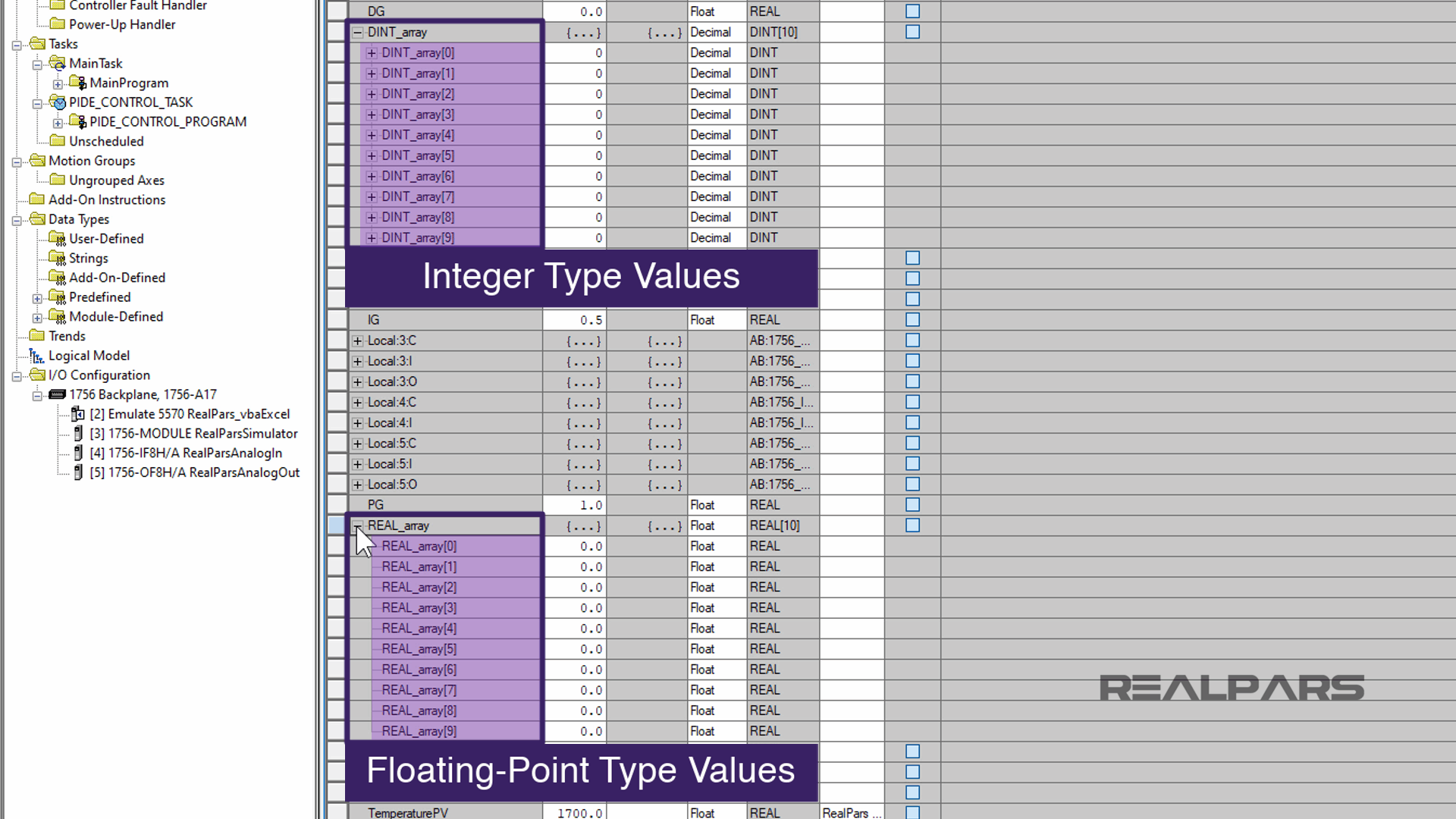
Next to the DINT_array and REAL_array tags, select the + sign next to the tags.
Once the + sign is selected, the tag array will expand to display all of the elements in the array.
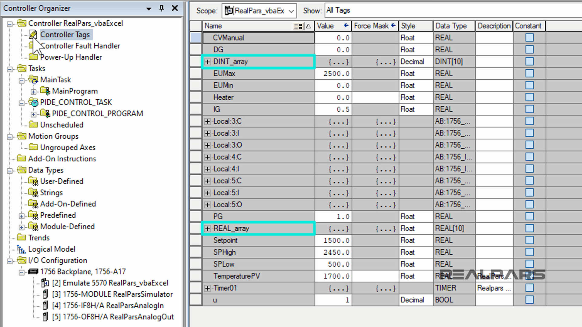
The DINT_array and REAL_array, each of them with 10 elements and the values we will enter to, allow us to see the different values in Excel.
DINTs are integer type values and REALs are floating-point type values.
Now, save the Studio 5000 program.
Run Studio 5000 Logix Emulate Software
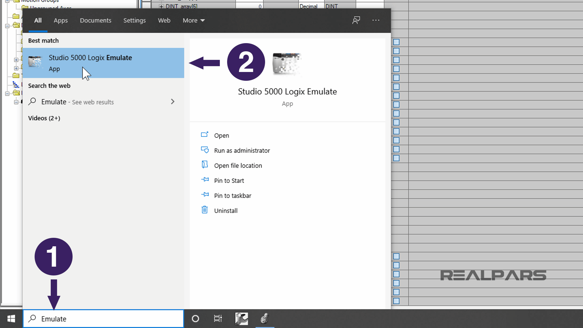
This is a good time to start up the Studio 5000 Logix Emulate software. The emulate software will emulate a virtual Rockwell Software PLC on a personal computer.
Locate the Studio 5000 Logix Emulate icon by selecting the Windows Start Menu, and then type Emulate to find Studio 5000 Logix Emulate software application from the list.
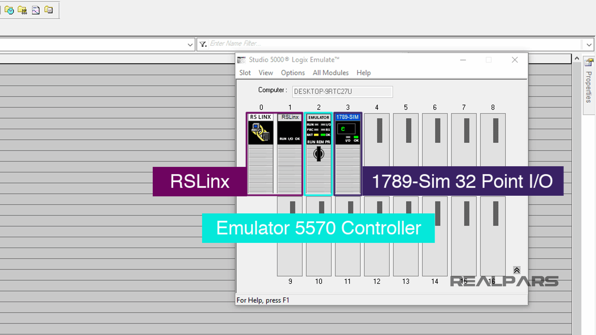
Setting Up the Emulator Modules
We have already setup the emulator, with the Emulator 5570 controller in slot 2, RSLinx in slot 0 and 1, and a 1789-Sim 32 Point I/O module in slot 3.
Run RSLinx Classic Communication Software
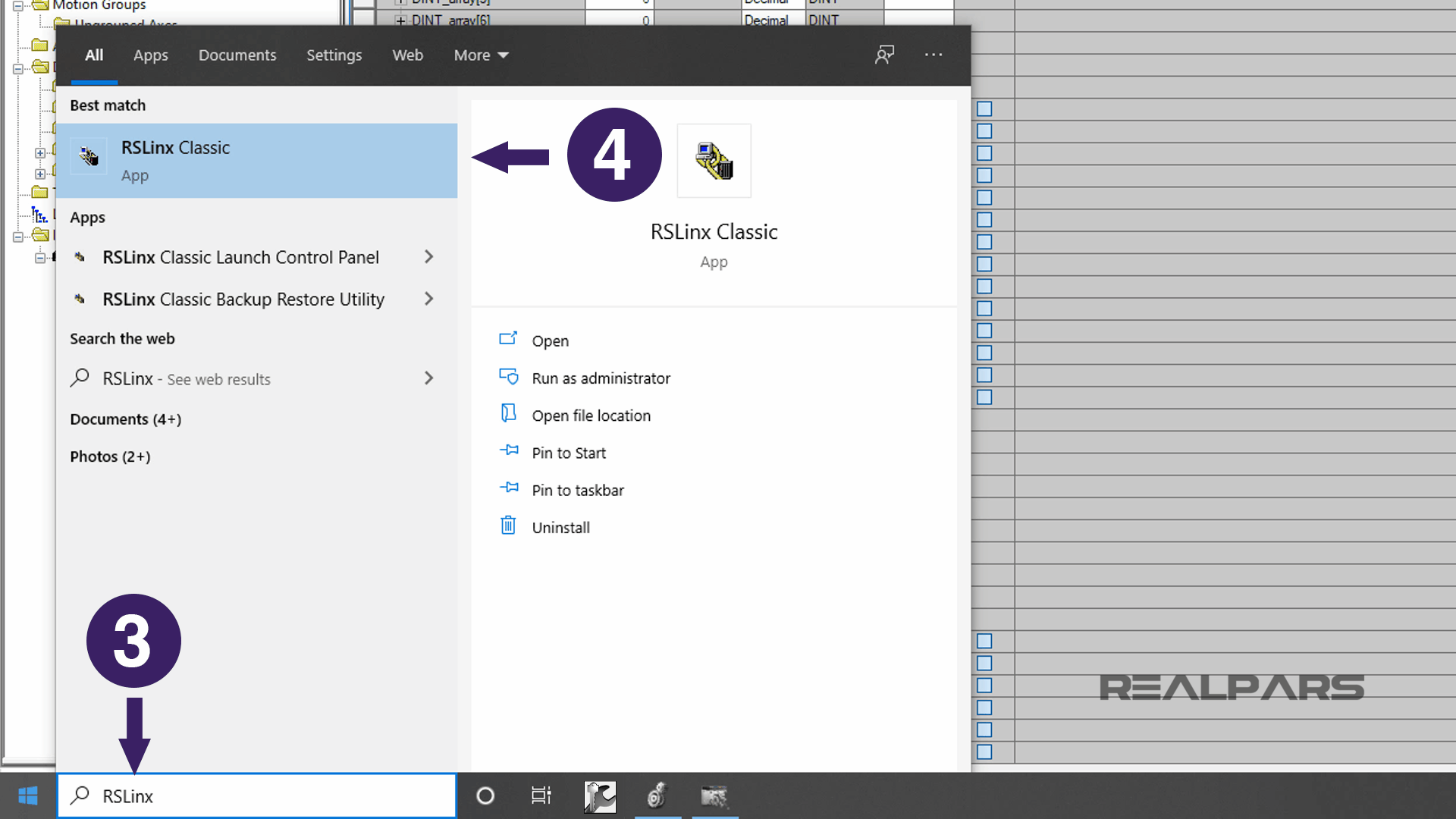
Now, let’s select the Windows Start button again to startup RSLinx Classic communication software.
Select the Windows Start Menu button and then type RSLinx to find the RSLinx Classic Desktop application.
Select the RSLinx Classic application from the list.
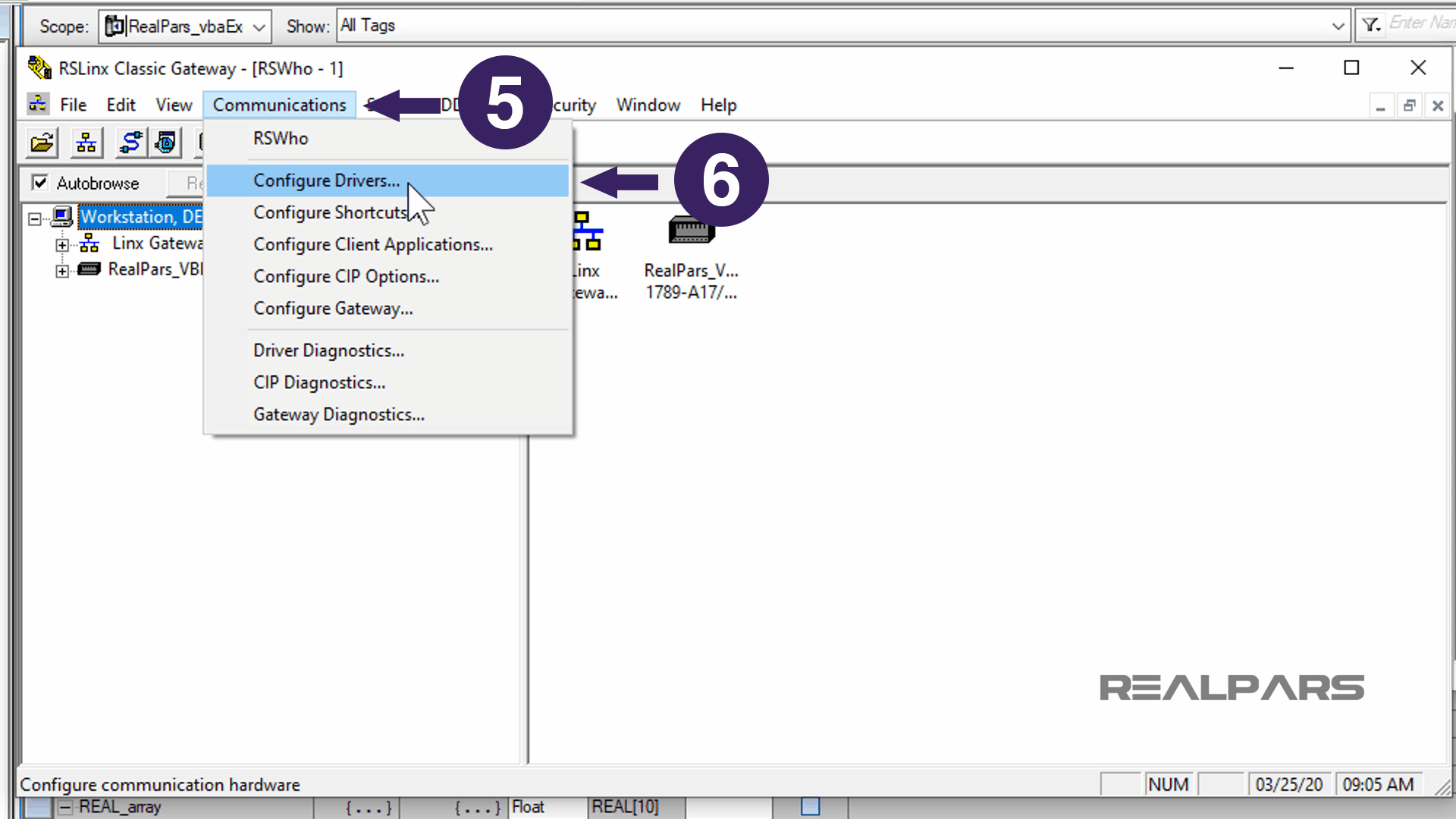
RSLinx will start.
The communication driver for the Studio 5000 Logix Emulator needs to be configured.
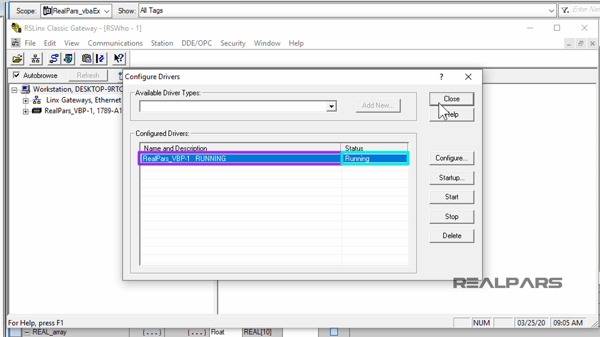
Select the Communications menu and then Configure Drivers.
In the previous article, we created the virtual driver called RealPars_VBP-1 which has a Running status.
Now If we select the DDE/OPC menu and then Topic Configuration from the drop-down list, we see the topic we’ve created in the previous article, called RealParsExcel.
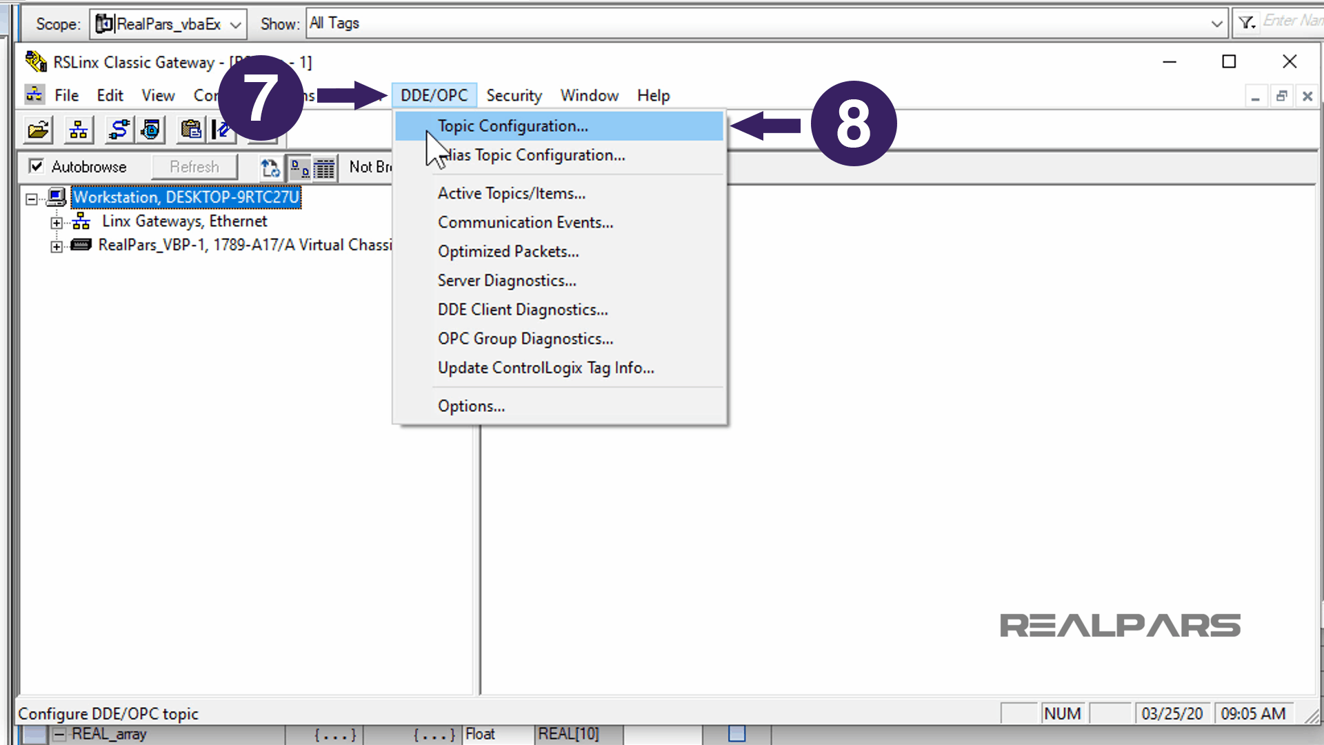

Ok, we are done with RSLinx Classic, for now.
We will download the Studio 5000 Logix Designer program to the virtual PLC.
In the Studio 5000 Logix Designer software, from the Communications menu, select Who Active.
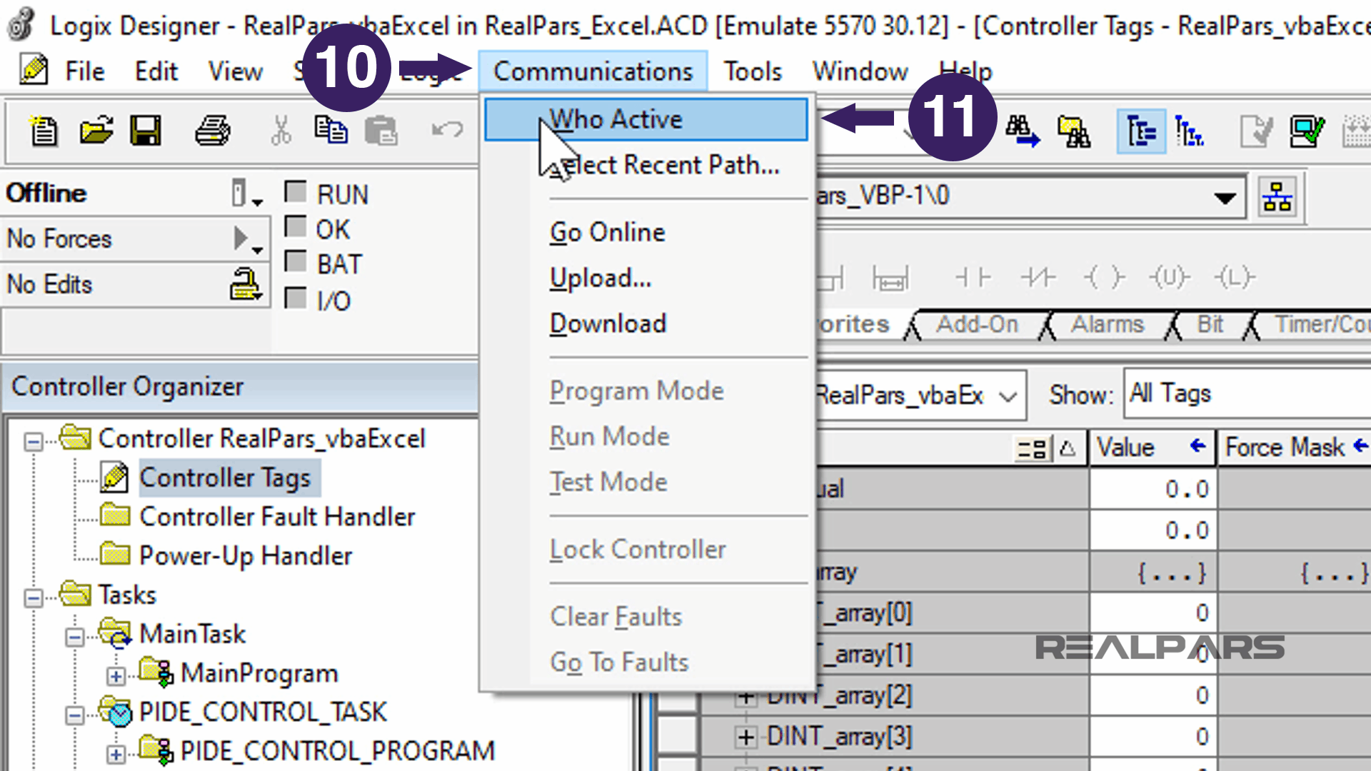
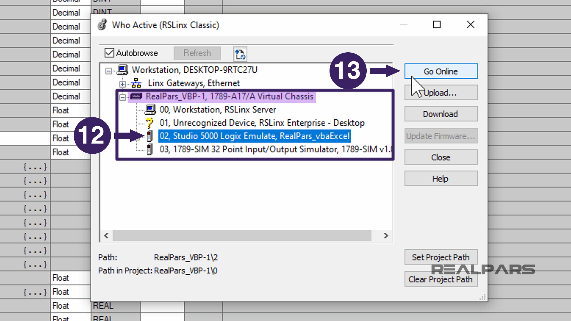
The Who Active window will appear, displaying all of the configured drivers, in this case, the Realpars_VBP-1 driver.
Select the Studio 5000 Logix Emulate from the list and then press the Go Online button.
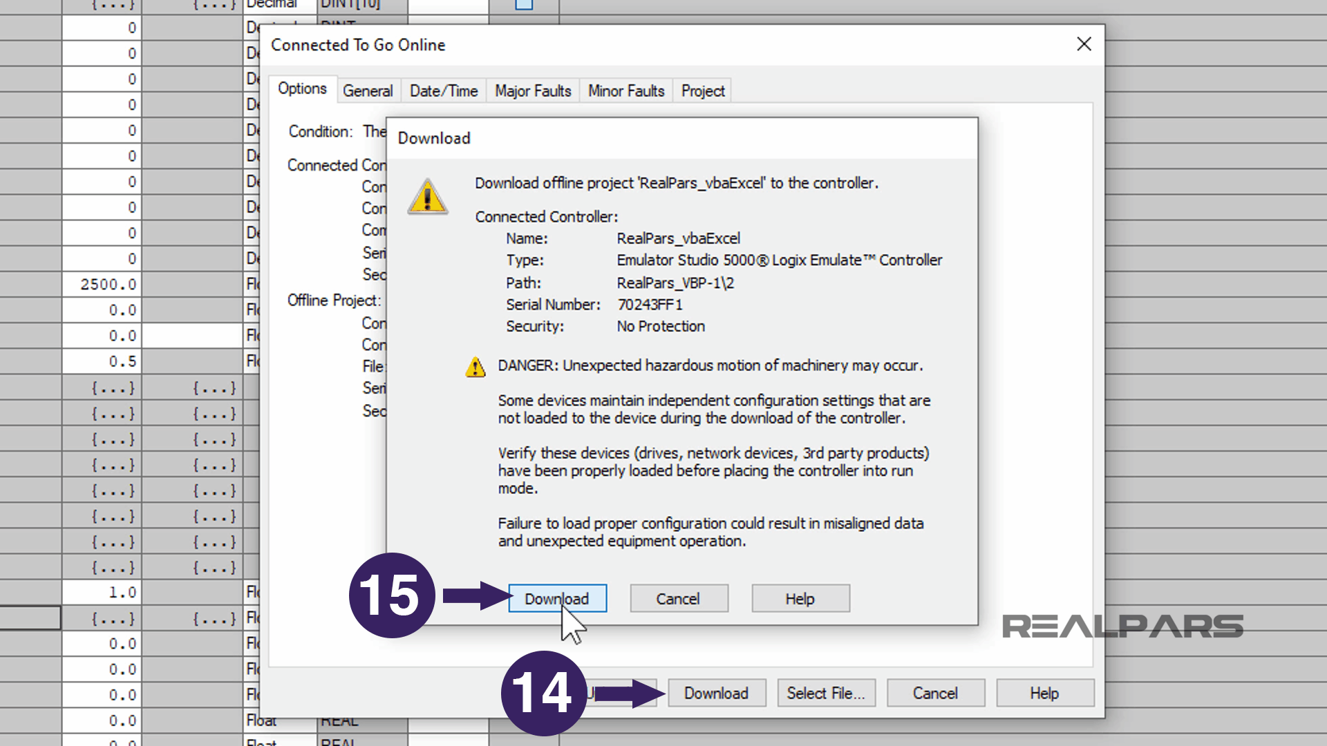
Download Program to Emulator
In order to download the program to the Emulator, In the Connected to Go Online window, press Download.
The download warning popup will display; select Download again to begin the download process.
After the Downloading, the progress bar completes to 100%.
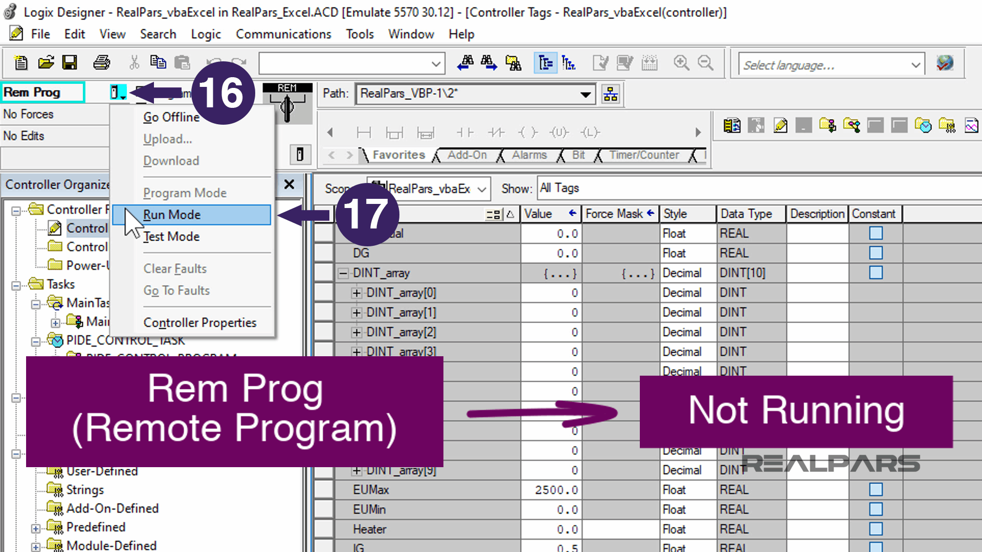
Now, return to the Studio 5000 Logix Designer program.
Notice that the controller is in Remote Program, which means the controller is not running.
Change the Remote Program state to Remote Run.
Select the icon next to the Remote Program indicator and from the list, select the Run Mode.
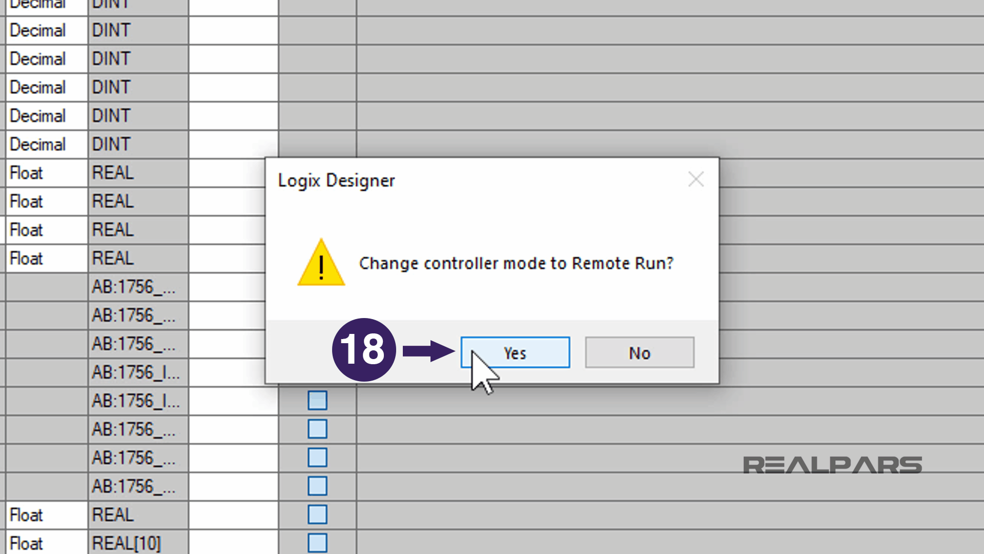
A configuration window appears asking to confirm putting the controller in Remote Run, select YES.
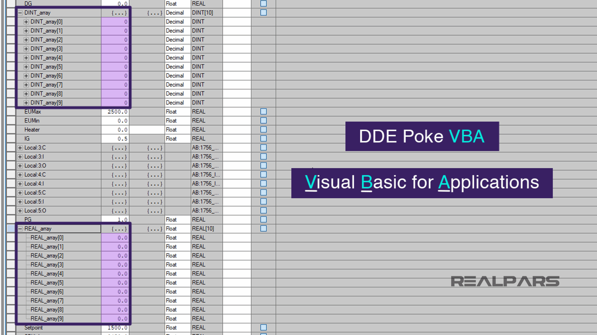
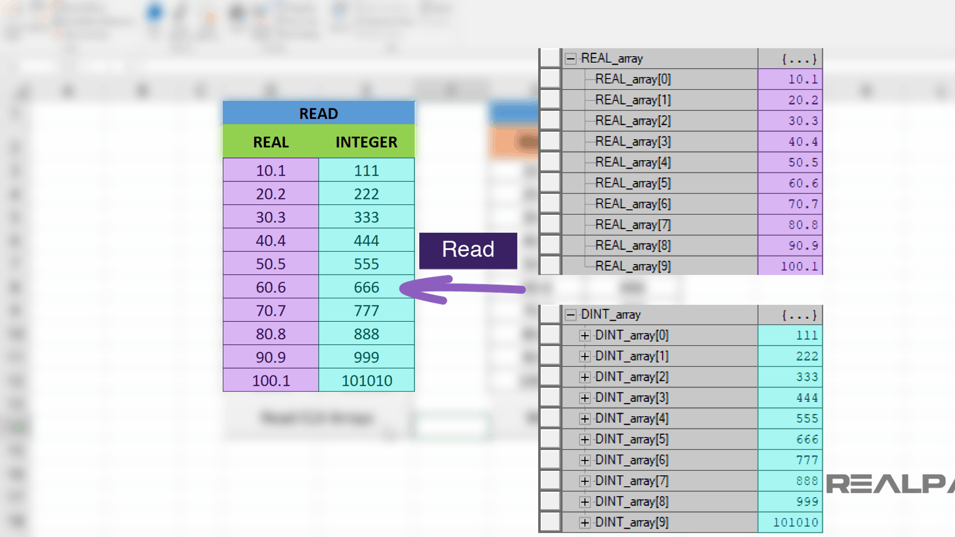
Now, let’s look at the Controller tags DINT_array and REAL_array that we added before and prepare to visually monitor the tags for the Excel Read and Write operation.
We are now ready to set up the DDE Poke VBA (Visual Basic for Applications) scripts for the READ and WRITE Control buttons in Excel.
Open Microsoft Excel Project
Now open up the Microsoft Excel project, which we’ve already created.
You can download this Excel file here.
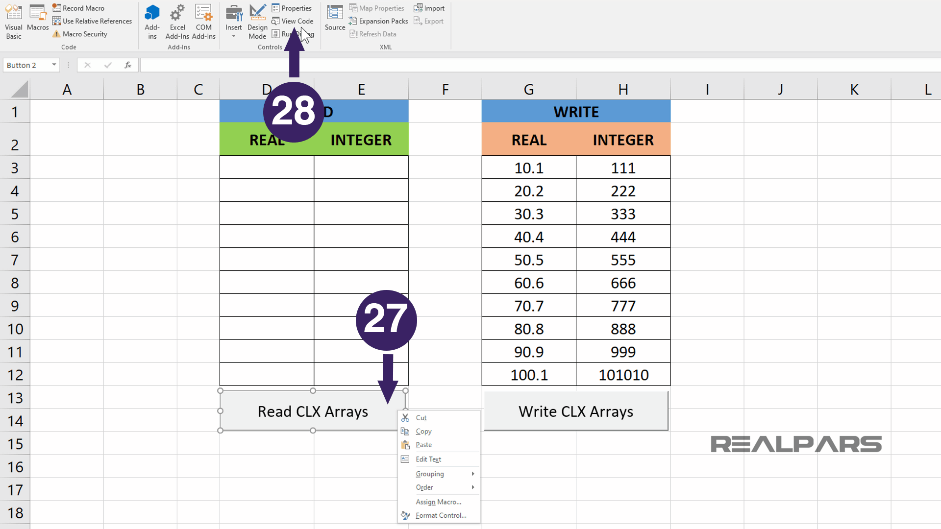
Starting with Sheet 1, we’ll rename the sheet to READ WRITE PLC.
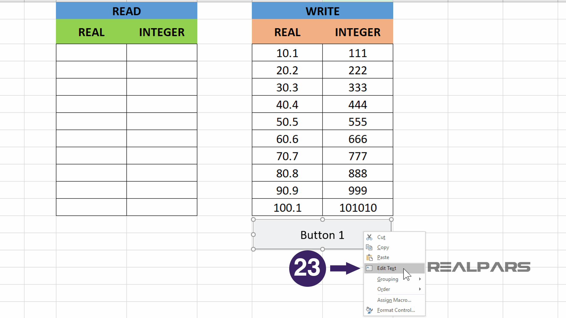
We named the D-E columns for READ and columns G-H for WRITE to identify where the data will be displayed.
Columns D-E will be READ Real and Integer data and columns G-H will be WRITE Real and Integer data.
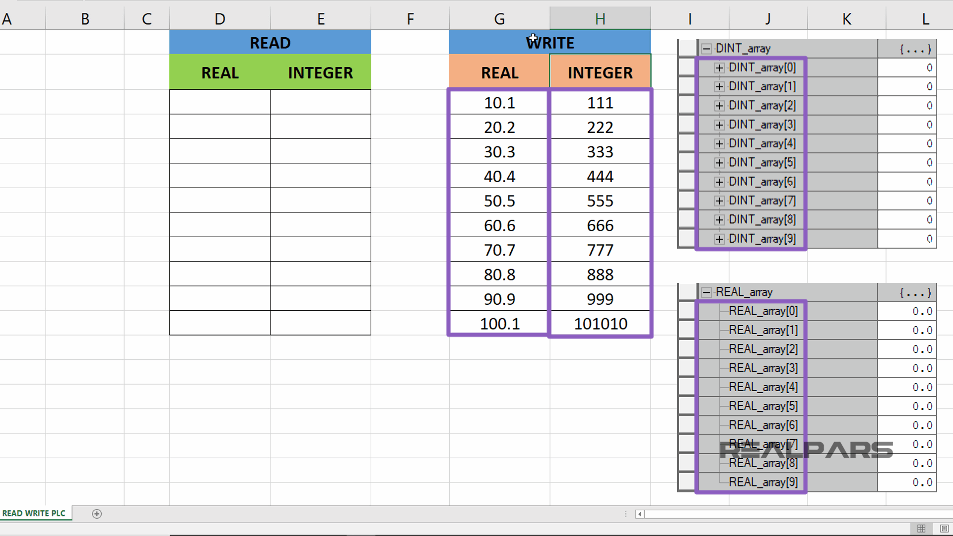
Remember our PLC tag arrays have been assigned 10 elements each (DINT_array [0] to [9] and REAL_array [0] to [9] ).
In the WRITE REAL CLX Values G column, we entered the floating-point values we want to write to the PLC and in the WRITE INTEGER CLX Values H column, we entered the integer values we want to write to the PLC.
VBA Scripting
In the next few steps, we will use VBA development mode and use VBA scripting to perform the write operation.
In order to place command button objects on the Excel sheet, we will enter into developer mode.
Create Form Controls Button Objects
To do this, select the DEVELOPER tab and then select the Design Mode button, this will allow you to place control objects on the sheets.
These control objects are essentially allowing us to create an HMI (or Human Machine Interface).
Next, let’s select the Insert button.
This button provides an assortment of controls for my Excel sheet.
Pressing the Insert button from the Menu displays a Form Controls drop-down menu. From this drop-down menu selection, pick the Form Controls-Button object.
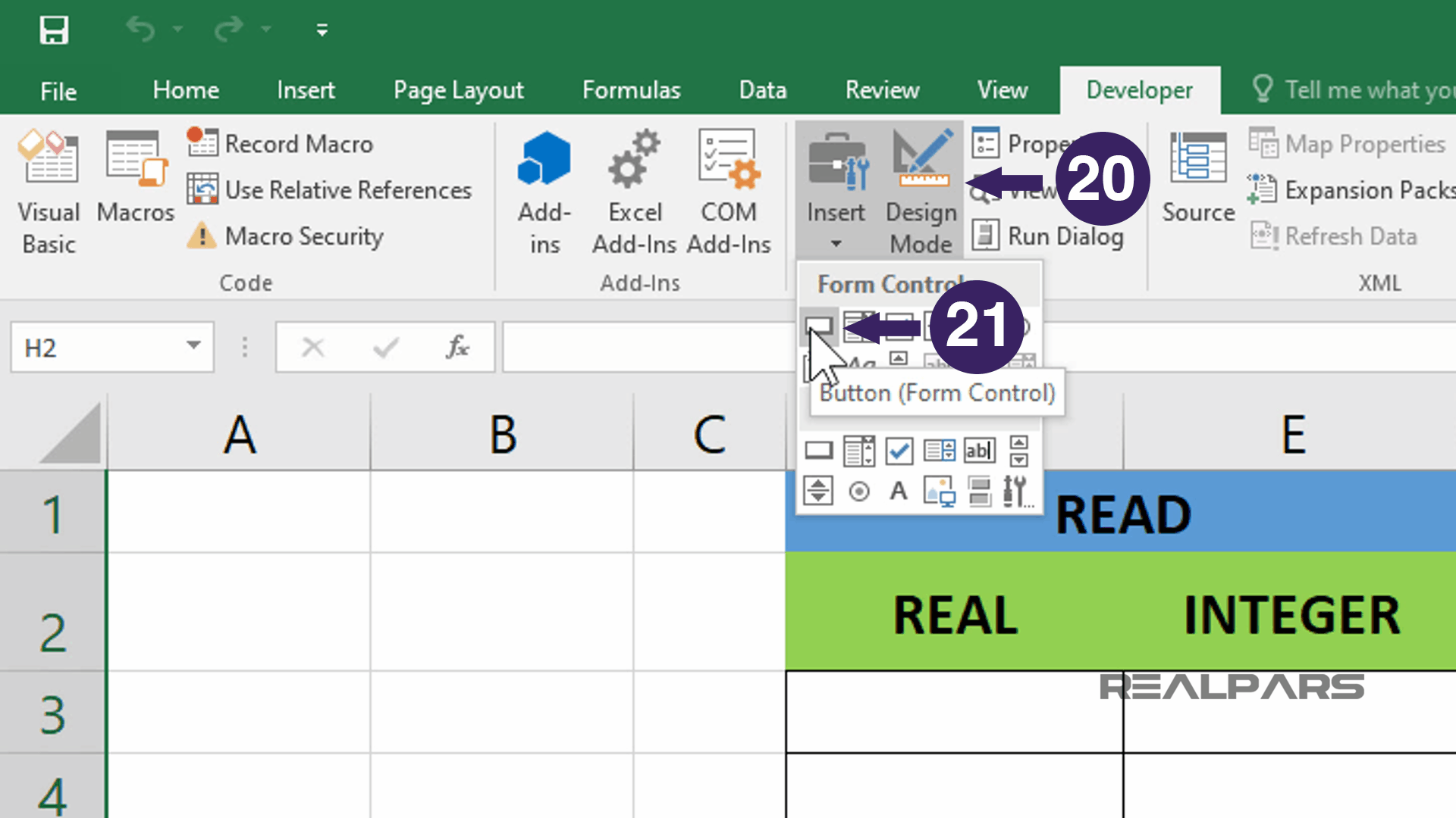
Once the command button is selected draw a rectangle below the data under the columns G-H.
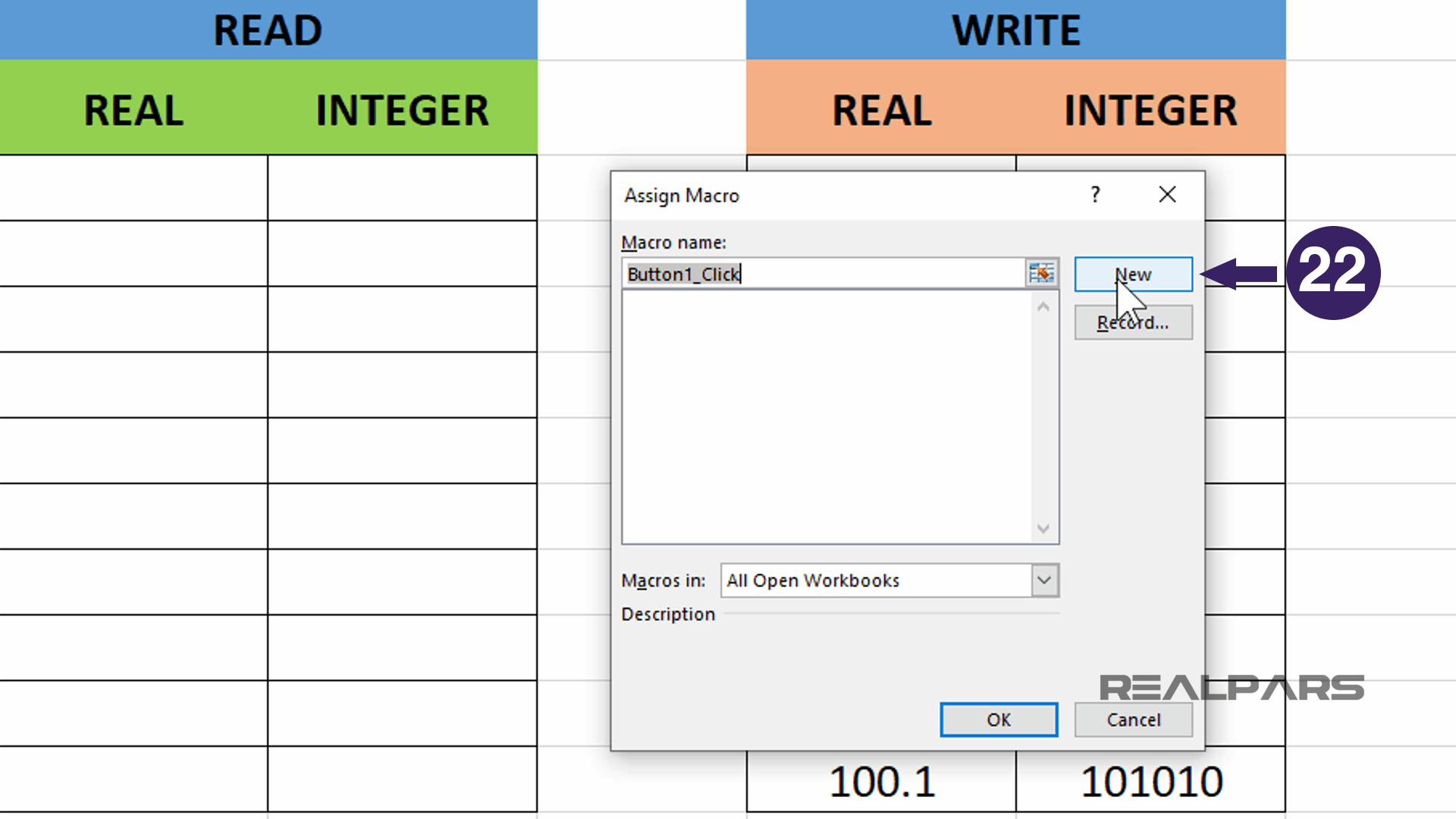
An Assign Macro window will appear, select the New button to create a new button.
Now the new button will appear. Let’s give the button a new name.
Right-click over the button and select Edit Text. Then enter WRITE CLX ARRAYS for the new name.
When completed, the Write CLX Arrays button appears with the new name entered.
Visual Basics for Applications (VBA) Window
Ok, here’s where the fun begins.
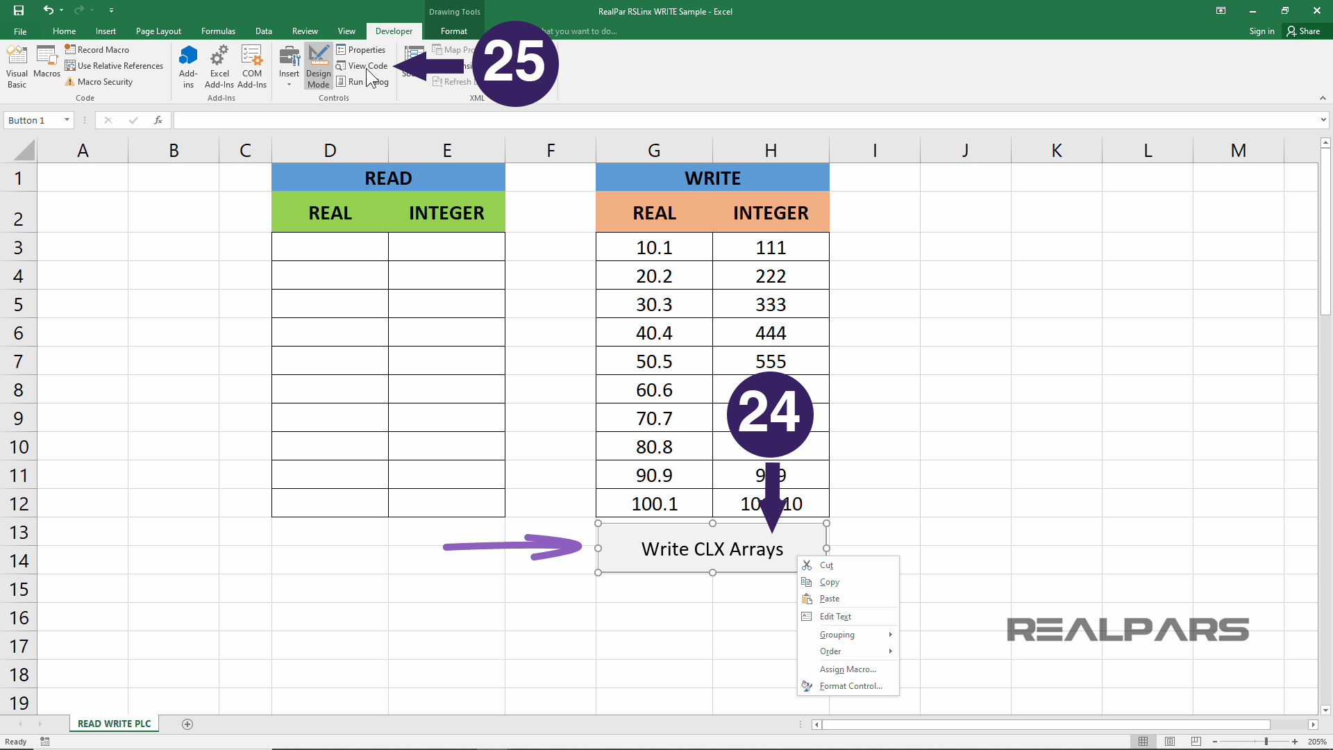
Right-click the WRITE CLX Arrays button, handlebars will appear around the command button.
In the Excel Developer menu area, select the View Code item.
The Visual Basics for Applications window will appear.
VBA RSLinx Connection
For the sake of simplicity in this article, we will write the VBA code that will perform much of the VBA RSLinx connection and write operation to the PLC and explain the VBA code in part.
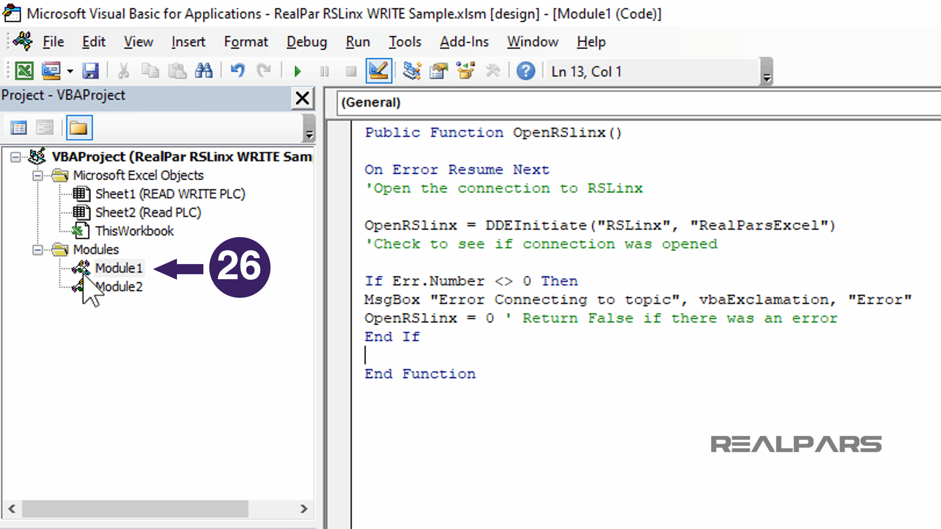
Under the Modules folder, double-click the Module 1 and then write the RSLinx Open and Connect code.
DDE Poke Write Command Script
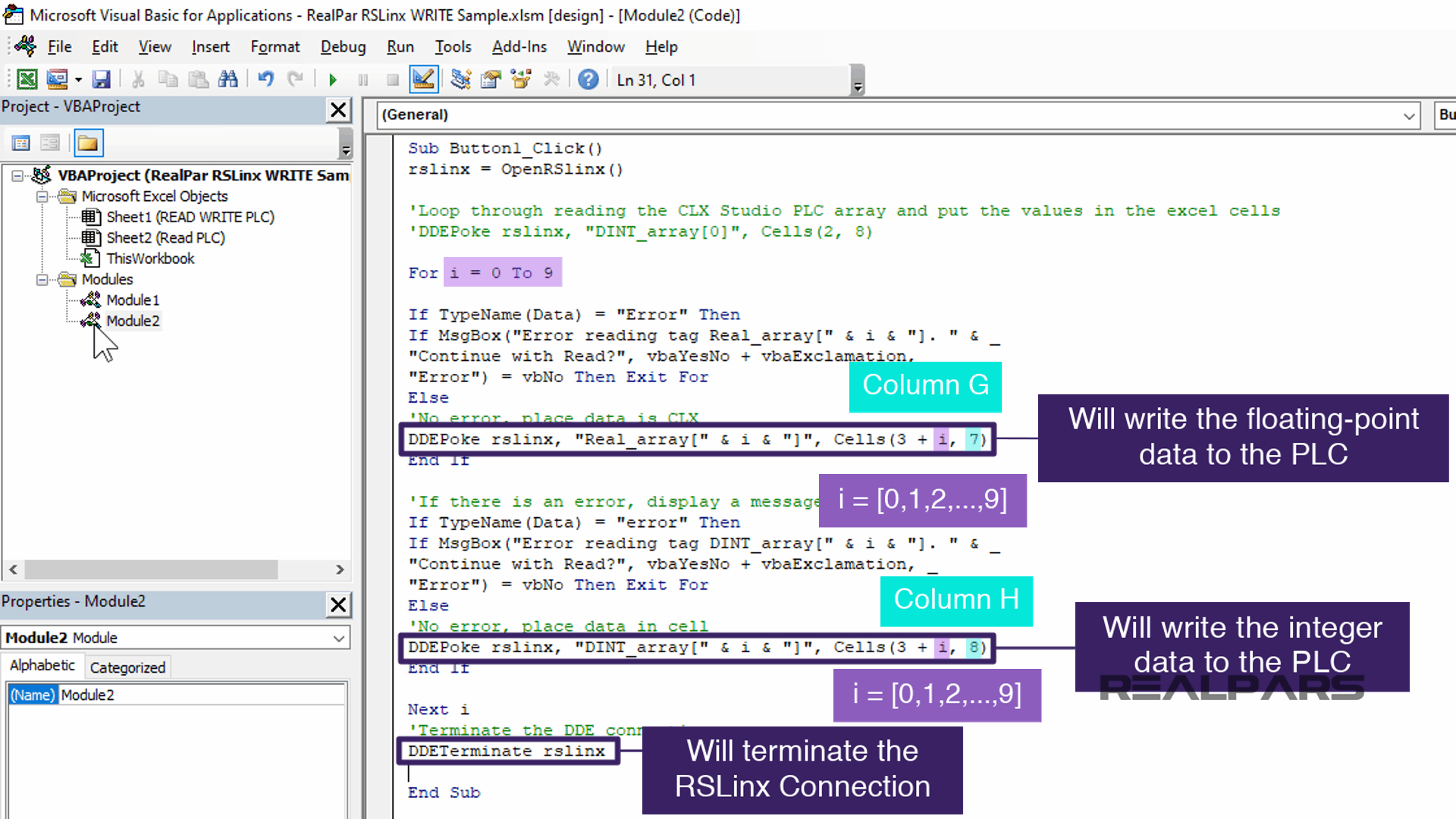
Next, we will write the DDE Poke Write Command script in the WRITE CLX ARRAYS button event area.
This Script for WRITE CLX Button event is CLICK and performs the connection to RSLinx and through RSLinx DDE communication to the PLC and finally, the DDE Poke function used to perform the actual write command when the button is left-clicked.
The script rslinx = OpenRSlinx() will OPEN a connection to RSLINX using DDE.
The For/Next Loop script will loop through for each of the Excel cells using the FOR NEXT instruction and display an error message box if there is an error.
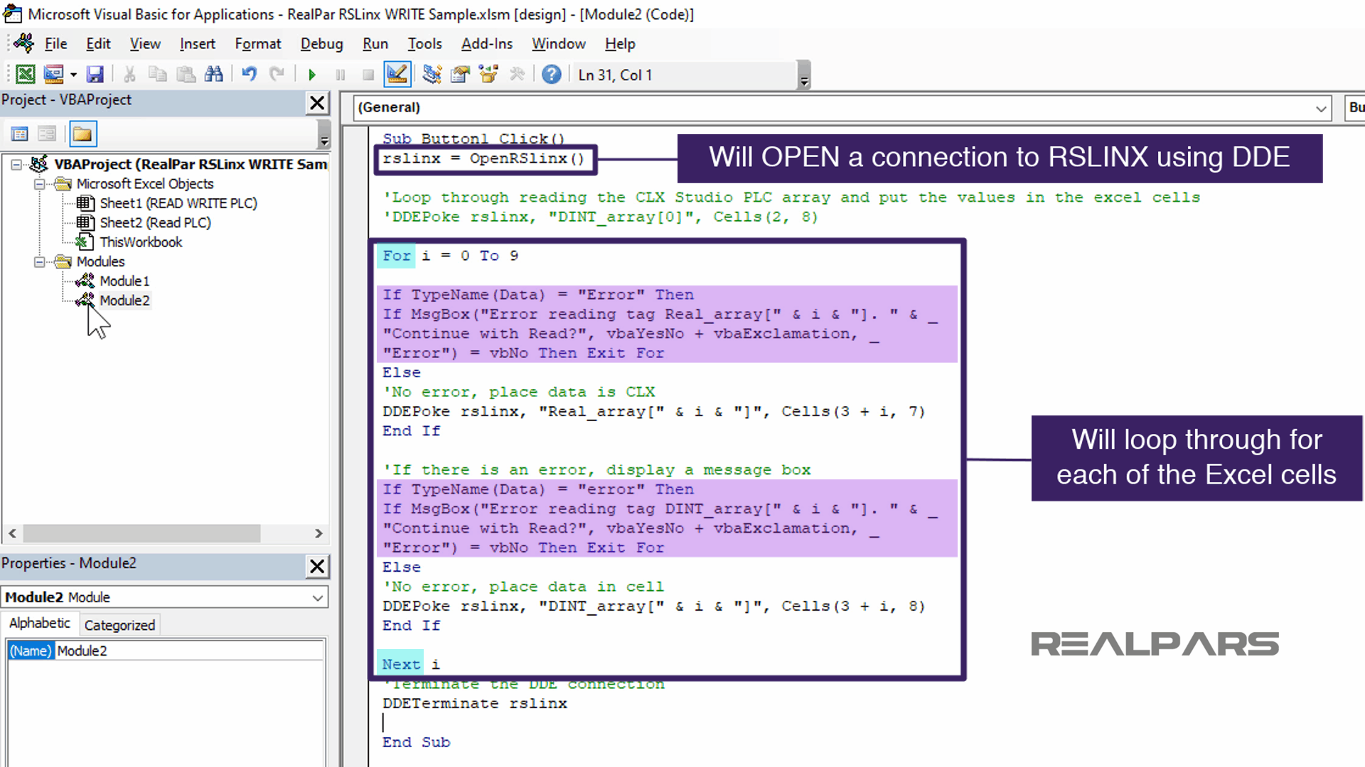
Two DDEPoke rslinx instructions will take the data and write the data to the PLC.
The first one, will take the REAL data in row 3+i, in column G and write the floating-point data to the PLC. With this loop, I= 0 through 9 and the number 7 represents column G.
The second one, will take the INTEGER data in row 3+i, in column H and write the integer data to the PLC. With this loop, i = 0 through 9 and the number 8 represents column H.
The instruction DDETerminate rslinx will terminate the RSLINX connection
Let’s test the Write CLX Array button.
With PLC online, we can see the values are all set to zero in the Studio Logix Designer controller tag window.
Now, Return to the Excel Write Command button.
Then left-click the command button. This action will run the script behind the button and write the values to the PLC.
Now let’s return to the Studio 5000 PLC program.
The Excel values in Column G and H are now available in the DINT and REAL array tags. Almost like magic.
VBA can be very powerful and perform many things.
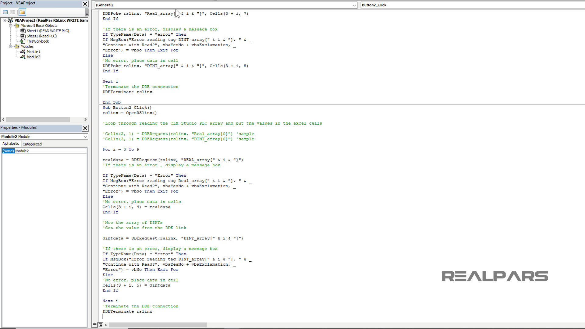
DDE Request Command Script
We performed the same operation as we did for the WRITE CLX Arrays command button to create the READ CLX ARRAYS command button.
After Right-click over the READ CLX ARRAY command button, select the view code from the Developer tab.
Write the code under the READ command button event.
Similar to the DDE Poke command, we will use the DDE Request method to read the data from the RSLinx DDE Topic.
Return to the Excel spreadsheet.
Left-click the READ CLX ARRAY button. The script will perform and read the values from the PLC controller tags.
We truly hope you have enjoyed learning what will support you in your upcoming Excel HMI based project.
If you would like to get additional training on a similar subject, please let us know in the comment section.
Want to Learn More?
If you would like to get additional training on a similar subject please let us know in the comment section.
Check back with us soon for more automation control topics.
Got a friend, client, or colleague who could use some of this information? Please share this article.
The RealPars Team
How to Configure Excel READ Communication from PLC (DDE) – (Part 1 of 2)
▶ How to Configure Excel WRITE Communication to PLC (VBA) – (Part 2 of 2)