

Temperature measurement in machines and other industrial processes is one of the key control variables used to guarantee the quality of products manufactured in different segments of the industry.
Currently, the two most used methods for electronic temperature measurement are applied through thermoelements: Resistive Temperature Detectors (RTDs) and Thermocouples.
In this article, we will cover what are Resistive Temperature Detectors, commonly known as RTDs, how they work, and how their signal is transmitted.
As the name itself gives away, a Resistive Temperature Detector is an instrument that detects temperature based on resistivity.

In order to understand the working principles of RTDs, it is essential to understand what electrical resistance and specific electrical resistance are, what causes it, and some basic fundamentals of it.
Electrical resistance
Electrical resistance is defined as the ability of a body to oppose the flow of electric current.

The standard international unit of resistance is the Ohm (Ω), named after the German physicist George Simon Ohm, and represents the volt/ampere ratio.
A substance that has free electrons and where the charge can move relatively freely is called a conductor.
When a conductor is subjected to a potential difference, such as being connected to a battery, an electric current passes through it, which is constituted by the movement of free electrons inside the conductor.
When these free electrons get into motion, they begin to collide with each other and with the atoms in the conductor.
Note that every conductor – and actually every material – is composed of atoms. These atoms are constantly slightly vibrating due to their energy.
The greater the number of collisions, the greater the difficulty encountered by the electric current in crossing the conductor. This difficulty in moving charges is what characterizes electrical resistance.

Effective factors
Electrical resistance varies depending on the length, width, and nature of the conductor material, as well as the temperature to which it is subjected.
Resistance is directly proportional to the length of the conductor, that is, the longer the length, the greater the resistance.
It is also inversely proportional to the area of the conductor, since the larger the area, the easier the passage of electrons and, consequently, the lower the resistance of the material.

Electrical resistance can also vary according to the variation of voltage and electric current in a conductor.
This is because the greater the intensity of the electric current, the less difficulty the charge carriers face to move, that is, the lower the resistance.

The potential difference between the ends of a conductor is proportional to the current flowing through it.
Lastly and the most important for our article is temperature: When the conductor is heated, its atoms absorb this heat energy, resulting in an increase in vibration.
Now, when the electric current is crossing the conductor, the number of collisions between electrons and atoms increases, making it harder for the current to flow throw it.
How does an RTD work?
Now that we understand what resistance is, let’s look at our RTDs: The electrical resistance of metals increases as heat rises and metals become hotter, while it reduces as heat decreases and metals become colder.
From what we just learned, we know that means that as heat rises, the ability of a metal to oppose the flow of electric current also increases, therefore less current can flow.
On the other hand, as heat decrease the ability of a metal to oppose the flow of electric current is reduced, hence more current can flow.
RTD sensors use this variation in electrical resistance to measure the change in temperature.
In order for the readings taken by these products to be interpretable, the metals used in the sensors must have known and recorded electrical resistances.
The most popular RTD sensors are platinum ones, such as the PT100 and the PT1000 – which have 100 and 1,000 ohms of resistance at zero degrees Celsius, respectively, and nickel ones, such as the Ni500 – with 500 ohms of resistance at zero degrees Celsius.

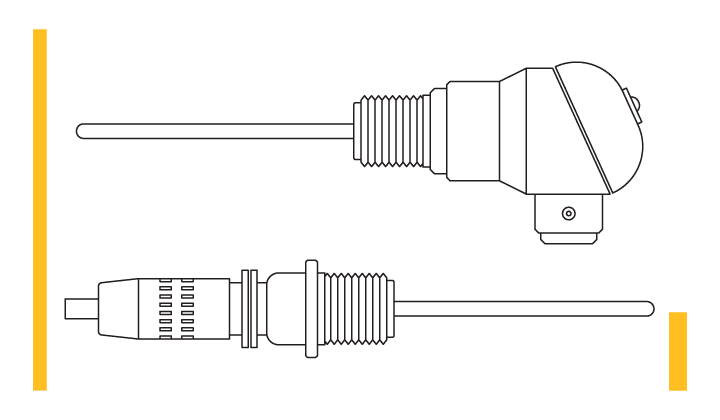
RTD components
Let’s take a look at the different components of an RTD: The Resistance or sensing element is the literal temperature detecting portion of the RTD. It is located at the end of the sensor, where it senses the actual process temperature.
It is a metal wire either on an etched grid on a substrate, or a wire wound in a coil. They can be made from numeral materials such as platinum, copper, nickel, among others.

The Protecting Tubing is mostly made out of stainless steel, which can be used for assemblies up to 500° F.
Since the assembly is often exposed to outside environment and moisture, this tubbing adds protection to the device.
The Process Connection is a standard fitting.

There are several wire configurations of RTDs available: 2, 3, and 4 wire.

The 3 wire RTD is the most commonly used in industrial applications,
As we previously talked about, the unit given by our RTD is in Ohms. We need to convert this delta in resistance to a delta in voltage or current to use this signal.
This is done by connecting the wires from our RTD to a transmitter, a PLC, DCS, or even a PID controller.

A bridge circuit known as the Wheatstone bridge is used for that purpose:
The Wheatstone bridge is composed of three resistors, a power source, a voltmeter or a voltage transducer.
The bridge is at null balance when the measured current flow of the two legs of the bridge is zero – that is the zero setpoints of the RTD’s output temperature.
As the temperature increases, the voltage, or current read by your voltmeter or voltage transducer also increases.

Summary
Now let’s wrap up what we have learned today:
– RTDs are devices whose operating principle is based on the variation of the electrical resistance of their conducting elements due to the temperature variation in the environment to which they are submitted.
– RTDs are sensing instruments that consist of resistive material – which is usually made of platinum, copper, nickel, and others.
– They work on the principle that each metal has unique composition and resistance to electrical current.
A material’s resistance is relative to its change in temperature, as its atoms absorb more or disperse energy, making it harder or easier for electrons to flow throw it.
– Some sort of a temperature transmitter, which can also be a PLC module, DCS, or even a PID controller is needed to transform this measure resistance change into a useful signal such as voltage or current.
A Wheatstone bridge is used for that purpose.
So you want to get to grips with RTDs? We at RealPars have just the thing for you – our Master RTDs: Understand, Implement & Maintain. In this comprehensive lecture series, we’ll take each one of these crucial stages step-by-step: from installation, calibration, and maintenance all the way through troubleshooting. Don’t miss out on expanding your knowledge!