
.webp)
Here’s a scenario that plays out daily in a process control environment: A Control Room Operator reports an erroneous analog HMI reading of a tank level or a pipe flow rate. Is it a problem with an I/O device, a PLC module, or the PLC program?
This article will discuss how to attack a problem like this.
PLC programs rarely cause failures unless idle hands have been experimenting. In this article, we’ll assume that there are no program errors and that the fault originates in the physical I/O devices or a PLC I/O module.
Field devices, such as sensors, transmitters, and associated loop circuits, are the most common cause of issues, accounting for 85% or more of all failures. PLC I/O modules are becoming more reliable and fail less frequently than historically.
We will examine how to perform some basic troubleshooting using a Digital Multimeter and introduce you to a process calibrator.
Understanding PLC analog inputs
A PLC analog input, or AI, can originate directly from various field devices.
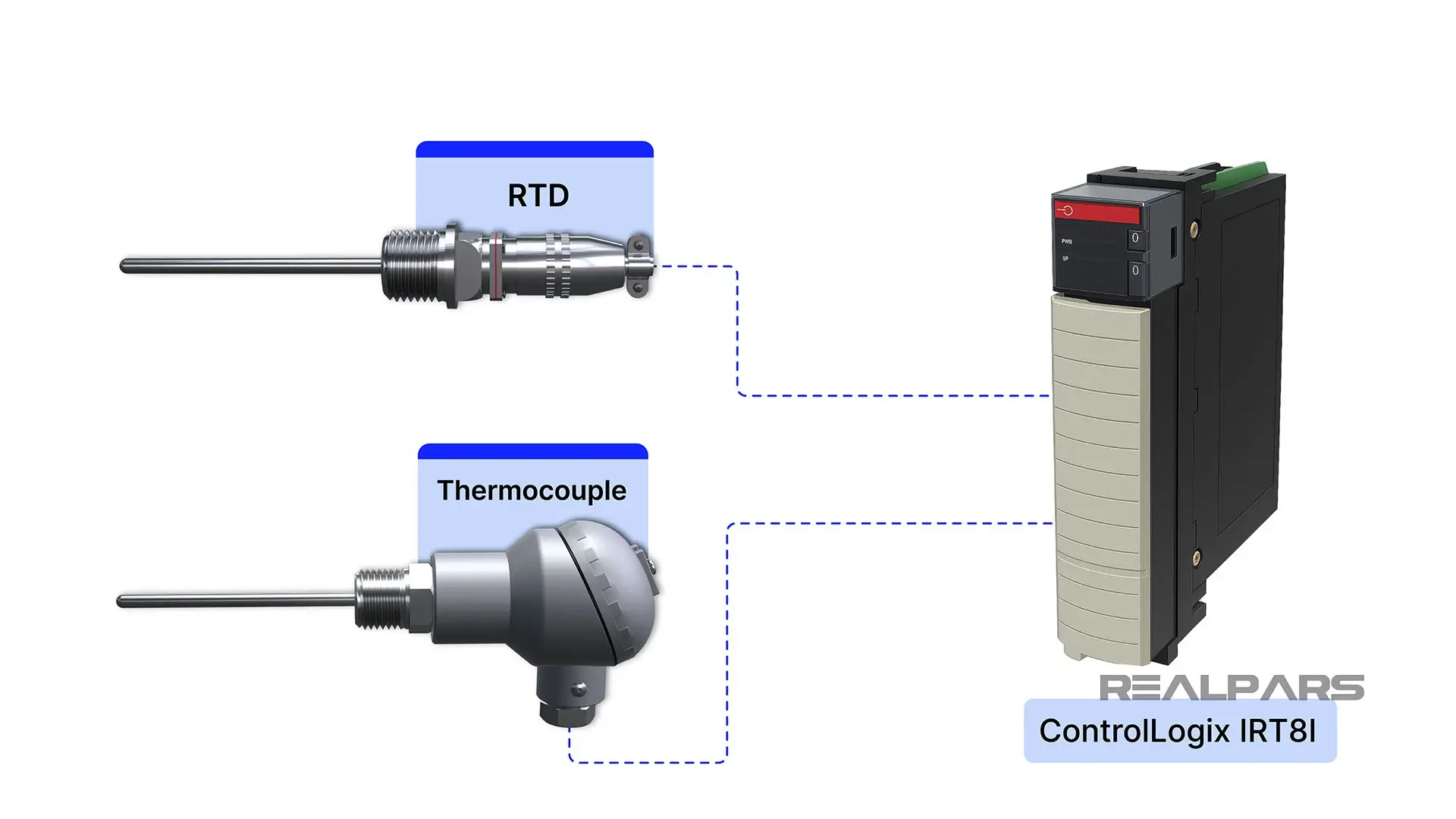
For example, special-purpose PLC AI modules can connect directly to temperature sensors such as RTDs or Thermocouples.
More commonly, PLC AI modules receive a standardized signal from a transmitter connected to a field device such as an RTD. The advantage of this type of generic PLC AI module is its flexibility, as it can receive signals representing many different process variables, including pressure, flow rate, and level.
We keep mentioning standardized signals. So, what are they?
A standardized signal is a voltage or current in a range representing 0 to 100% of the process variable being measured.
Common standardized signals include 4–20 mA for current loops, 1- 5V, and 0–10 V for voltage signals.
Level control loop example
Let’s examine a 2-wire current loop used to measure tank level, illustrating the use of a standard signal. The level transmitter will produce a 4 to 20 mA current over the 0 to 100% range of the tank level. When the tank level reaches 15 inches or 50%, the loop current is 12 mA, representing 50% of the 4 to 20 mA signal range.
If you're interested in learning how a transmitter can be physically wired and you're a RealPars member, you can check out this course on Transmitter Basics.
Alright….let’s talk about tools for troubleshooting PLC analog input modules and associated loops.
A Digital Multimeter is very useful for basic testing, and that’s what we’ll be using in this article.
A very versatile tool for testing, troubleshooting, and calibration is the Instrument or Process Calibrator. More on that later.
Ok…let’s go back to our Level Control Loop.
As we stated, this is a typical 2-wire control loop containing a transmitter, DC power supply, and a PLC analog input module. Keep in mind that the power supply is often used in other loops. We will show you a real-world example later.
The 4 to 20 mA current flowing in this loop represents the level of a tank.
A control room operator reports an erroneous HMI reading of 0% level when he knows that the tank is actually at 50%, as verified by an outside operator.
For now, we’ll focus on this basic circuit, assuming there are no other loops connected to the power supply.
As the troubleshooter, the first step is to identify potential faults.
It could be a defective transmitter, a faulty power supply, a malfunctioning PLC module, or a broken wire.
Using a digital multimeter
Let’s start by measuring the loop current with a DMM set to measure milliamps.
At first glance, it seems straightforward enough.
All you need to do is place the ammeter anywhere in series with any of the components in the loop, because basic theory tells us the current is the same everywhere in a series circuit. So, all we need to do is find a convenient location to insert the ammeter.
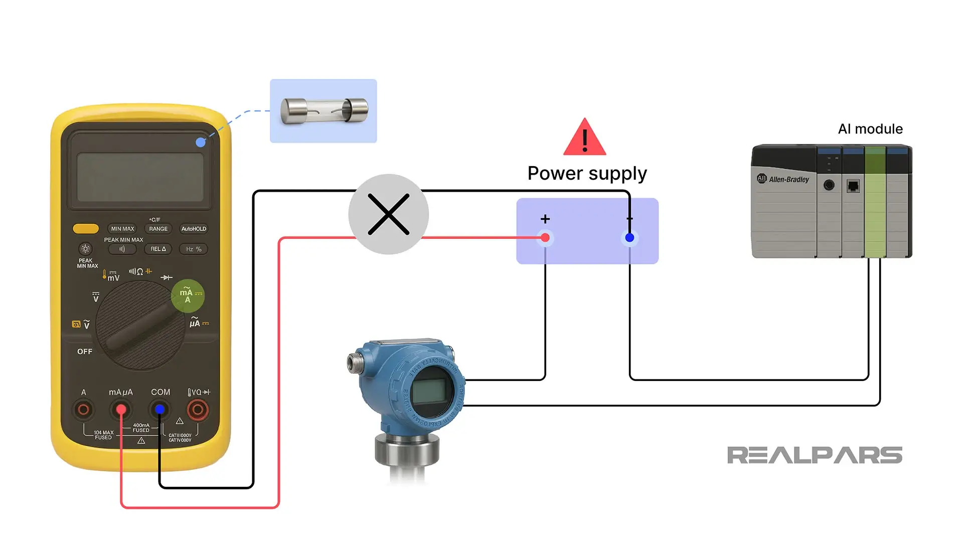
Unfortunately, the ammeter is often mistakenly placed across the power supply.
What’s wrong with that? An ammeter has zero ohms of resistance, which can cause the meter fuse to blow and potentially damage the power supply.
The circuit must be broken so that the ammeter can be placed in series, which may not be as easy as it sounds in a real-world environment.
Do you cut wires to insert the ammeter?
Are there terminal blocks where you can remove wires and insert the ammeter?
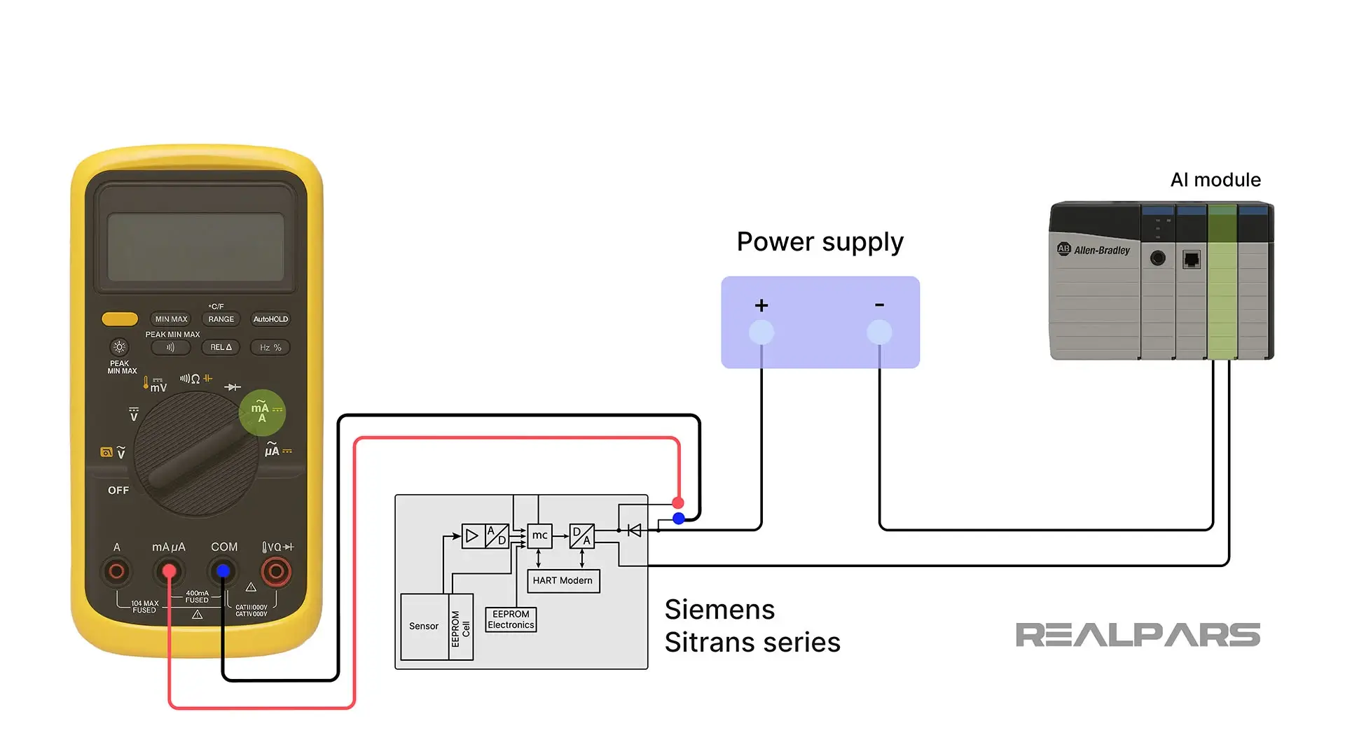
Some transmitters, like the Siemens Sitrans series, make it easy, allowing you to connect an ammeter across a pair of dedicated terminals to test for loop current.
But, more often than not, you must find a way to break into the circuit.
Updated drawings
Before you begin troubleshooting, you will need a complete set of updated drawings. We will assume we have what we need.
Let’s examine two drawings for a Level Loop in a plant.
Sheet 1 shows us an isolated view of the Level Current Loop. The Level Transmitter with the tag LT-YA255 sends a 4 to 20 mA signal to Channel 13 of the ControlLogix PLC Analog input module 1756-IF16.
Sheet 2 shows us the complete wiring diagram of the 1756-IF16 module. Please note that two other transmitters are utilizing this module.
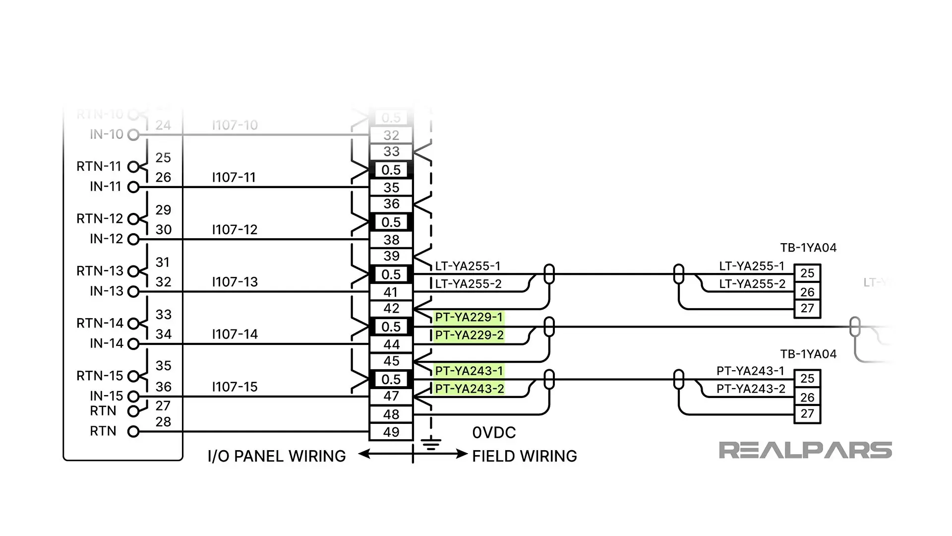
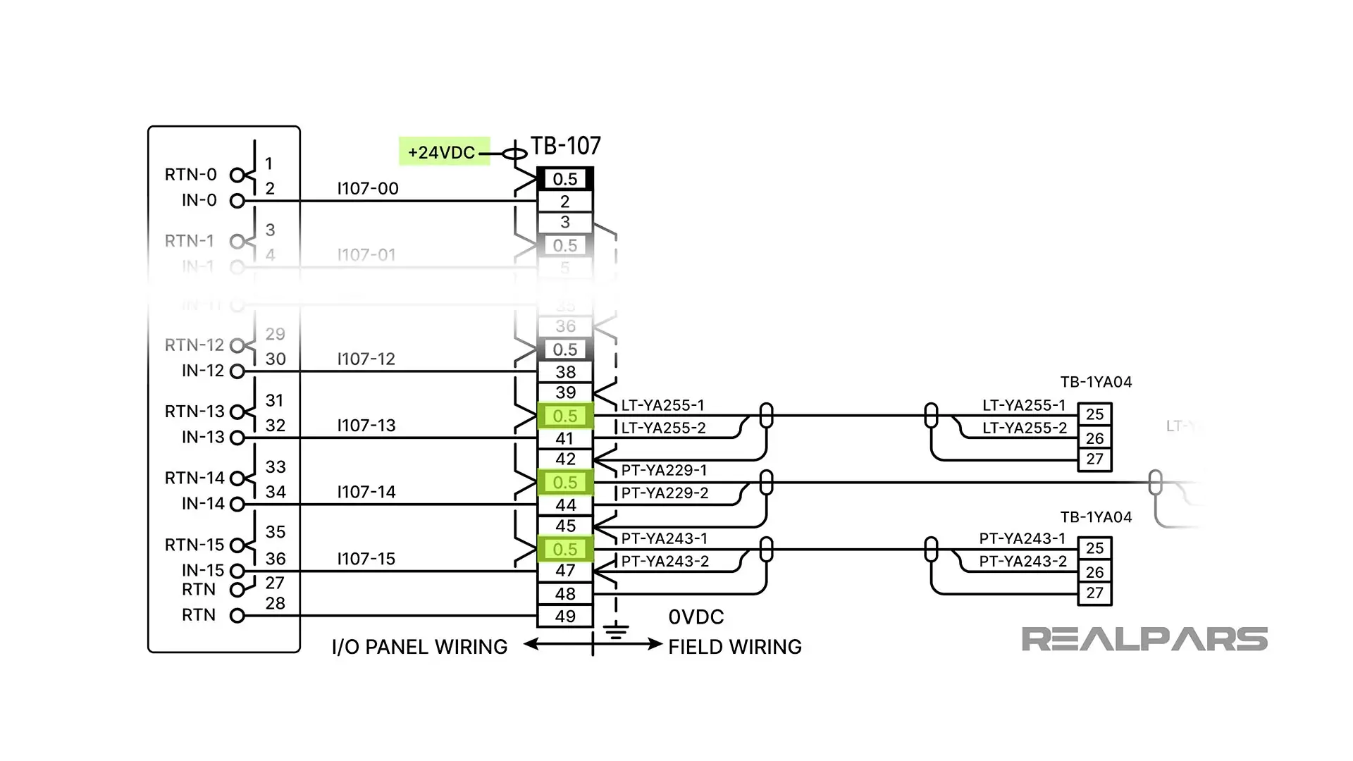
Notice how all three current loops share the +24V DC Power supply.
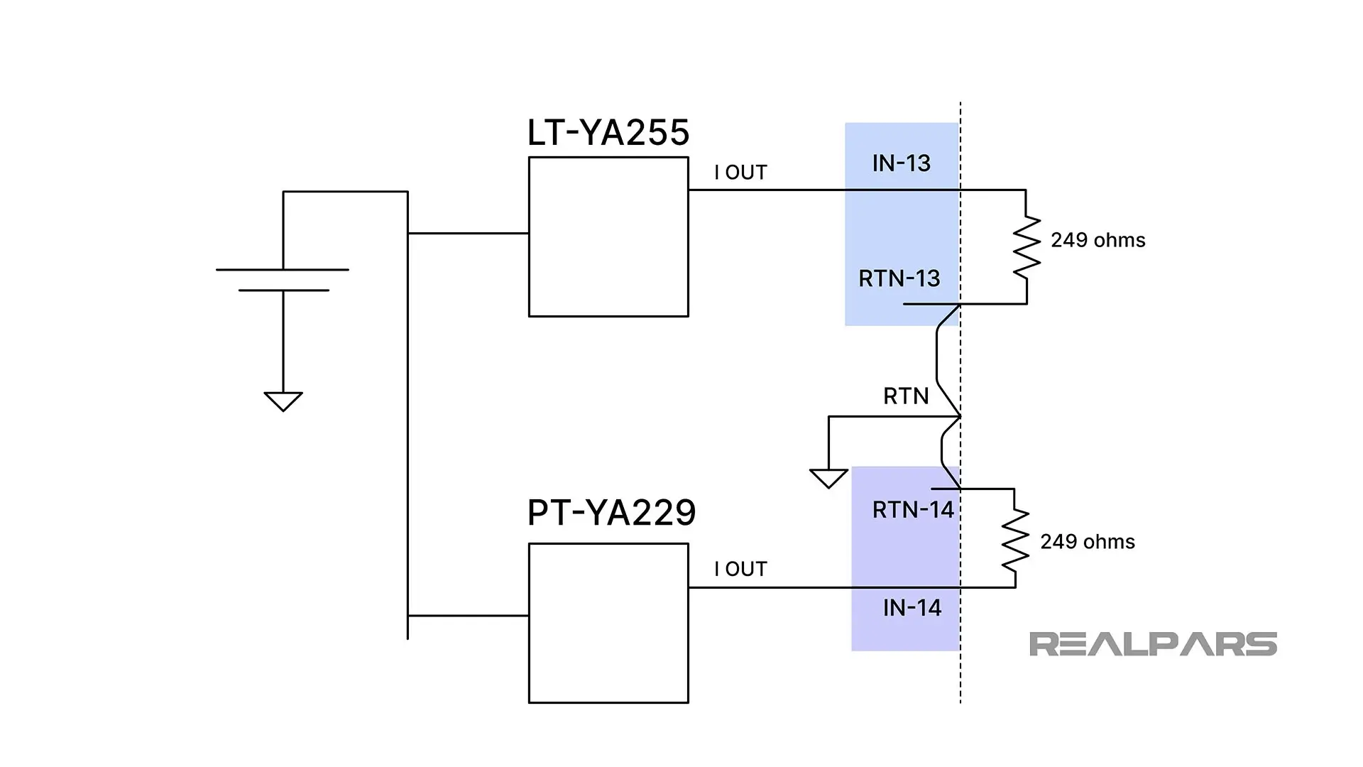
Here’s a simplified sketch of the Channel 13 and 14 loops.
Troubleshooting and measuring
Ok….back to our problem. Recall that a Control Room Operator reports an erroneous HMI reading of 0% tank level when he knows that it is 50%.
In our simple basic circuit, we suggested that a possible fault could be a defective DC Power Supply. In this case, that is highly unlikely because two other control loops share it, and the Operator would have seen other fault alarms on the HMI.
So, our first step is to measure the Level loop current.
There are at least 3 terminal block locations where you can remove a wire and insert the ammeter.
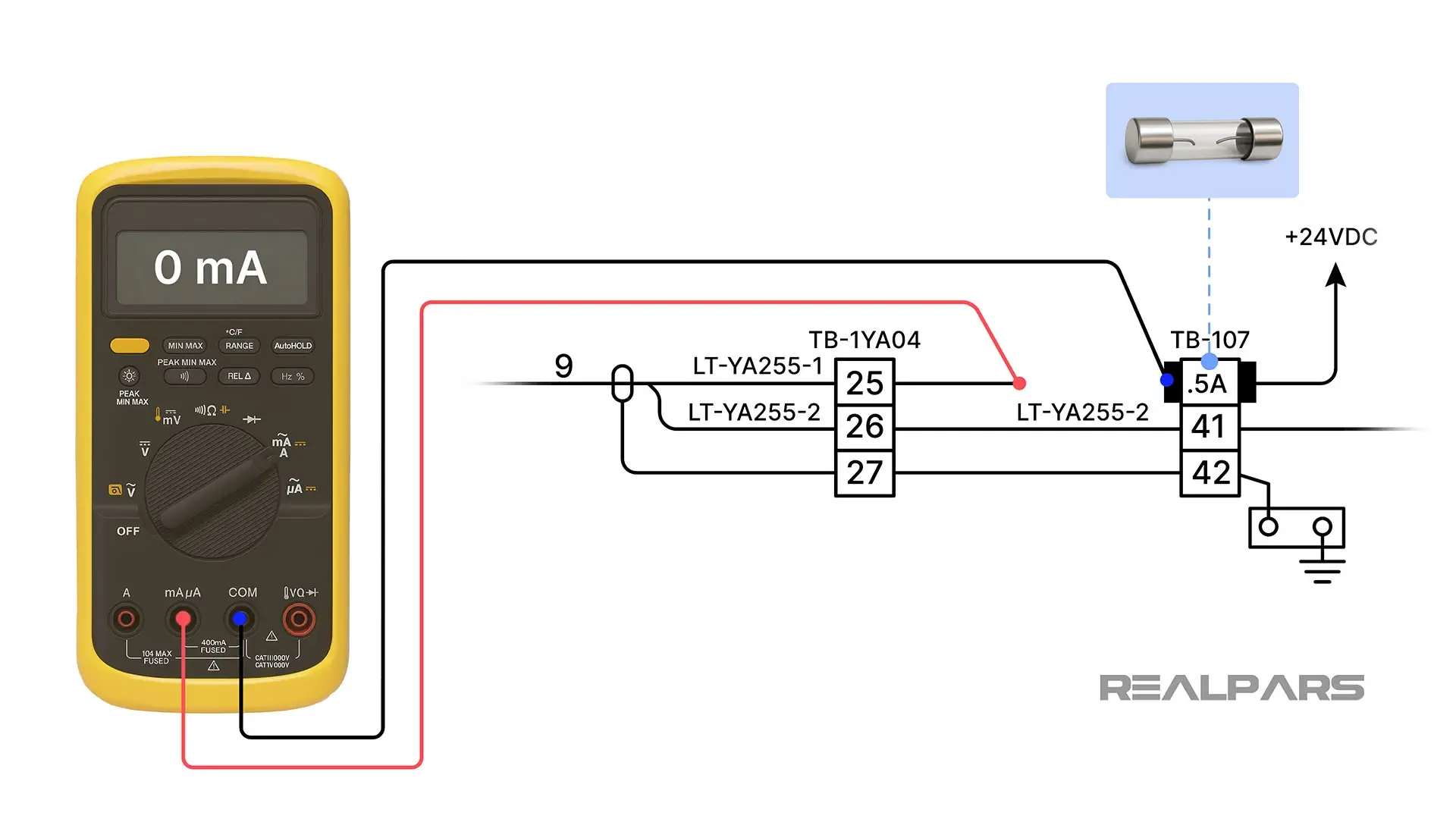
Let’s remove the wire from TB-107 that connects to Terminal 25 of TB-1YA04 and place our ammeter in series.
If the ammeter reads zero mA, the .5A fuse is likely blown, but further tests are required.
The next step is to measure the DC voltage on both sides of the .5A fuse with the DMM set to DC volts.
If you measure +24V on the supply side, and zero volts on the load side, it's time to change the fuse.
If you measure +24V on both the supply and the load side, the fuse is fine, and the fault is likely elsewhere in the current loop.
Using a process calibrator
Having a Process Calibrator is very advantageous at this troubleshooting juncture.
An Instrument or Process Calibrator in Simulate mode replaces or simulates a transmitter in a 2-wire loop configuration. The calibrator can be adjusted to supply known settable test currents, thus verifying the integrity of the other loop components and the Operator HMI.
If you want to learn more about instrument calibration, you can check out the course Industrial Sensor Fundamentals.
One final note: If you're a plant manager looking to train your team with RealPars courses, don’t forget to check out realpars.com/business.
And if you want to learn more, here’s a list of the courses we mentioned in this blog post:
Course #1: Industrial Sensor Fundamentals
Course #2: Transmitter Basics