
If you are involved in any way with industrial machinery, you almost have to have heard of ladder logic. Since there are almost never ladders involved, it probably doesn’t make a lot of sense that we call it that, but the reasons for the name are buried in the history of automatic controls. What is ladder logic?
At one time, automatic systems were controlled with relays.
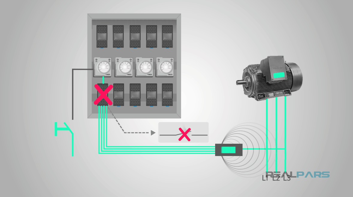
Relays are electromechanical devices and fail quickly as the mechanical parts wear out and the electrical parts are destroyed as the electricity they switch burns away the contacts.
They are big and use lots of electricity, generating lots of heat in the process.
Early automatic controls: relays
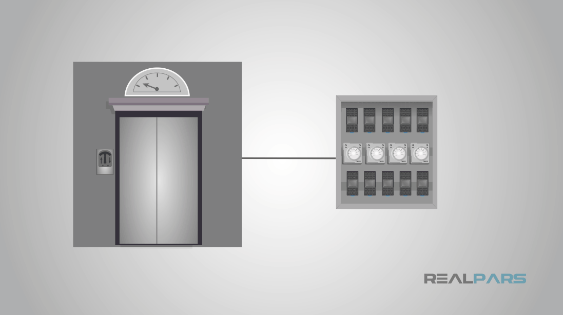
At one time, the only “automatic” device most people ever encountered was an elevator.
In modern-day control terms, the elevator is a simple application that is well understood.
Even so, a control system implementation in relays was a big, complicated affair.
Why is it called ladder logic?
In order to understand why we call it ladder logic, you need to look at how we document relay logic controls.
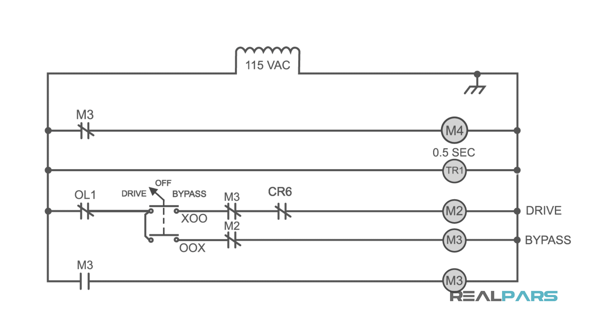
The actual “ladder” was the drawing of the control logic, an illustration of how the relays were wired together. Even today, a lot of the conventions that led to “ladders” are still in use, and I will use a recent example drawing to illustrate this.
Below is a simplified drawing of a control circuit and one of our ladder logic diagram examples. The appearance is what led to being called ladder logic, since it superficially resembles a ladder.
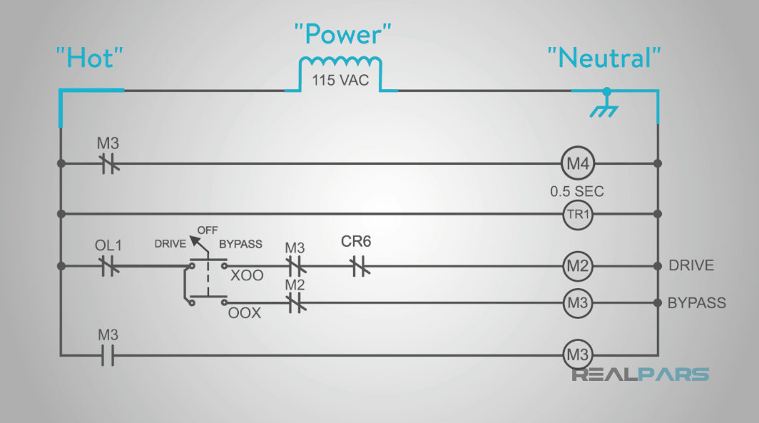
Other drawing conventions that survived into the software version include:
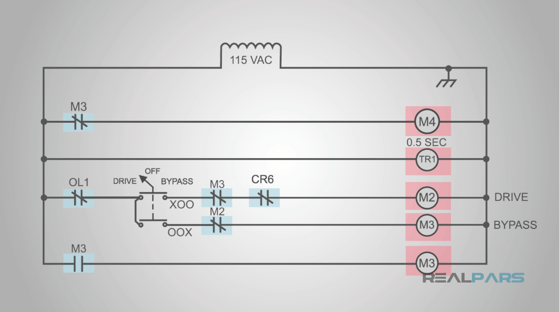
Power at the top of the drawing, with the hot or power rail going down the left side, and the neutral rail going down the right side.
We also have contacts or inputs on the left, and coils or outputs on the right, so that our power is flowing from left to right.
Finally, each of the outputs is on a separate horizontal line or, in our ladder metaphor, rung.
Another convention is that we always descend the ladder – we work from top to bottom.
Relays are simple devices, consisting of coils and the contacts that they move. When electricity energizes the coil, it moves the contacts, connecting some and disconnecting others. The lowest-level elements of ladder logic mimic those relay functions.
Ladder logic in PLC software
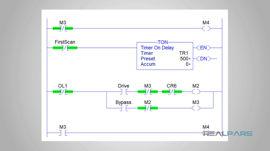
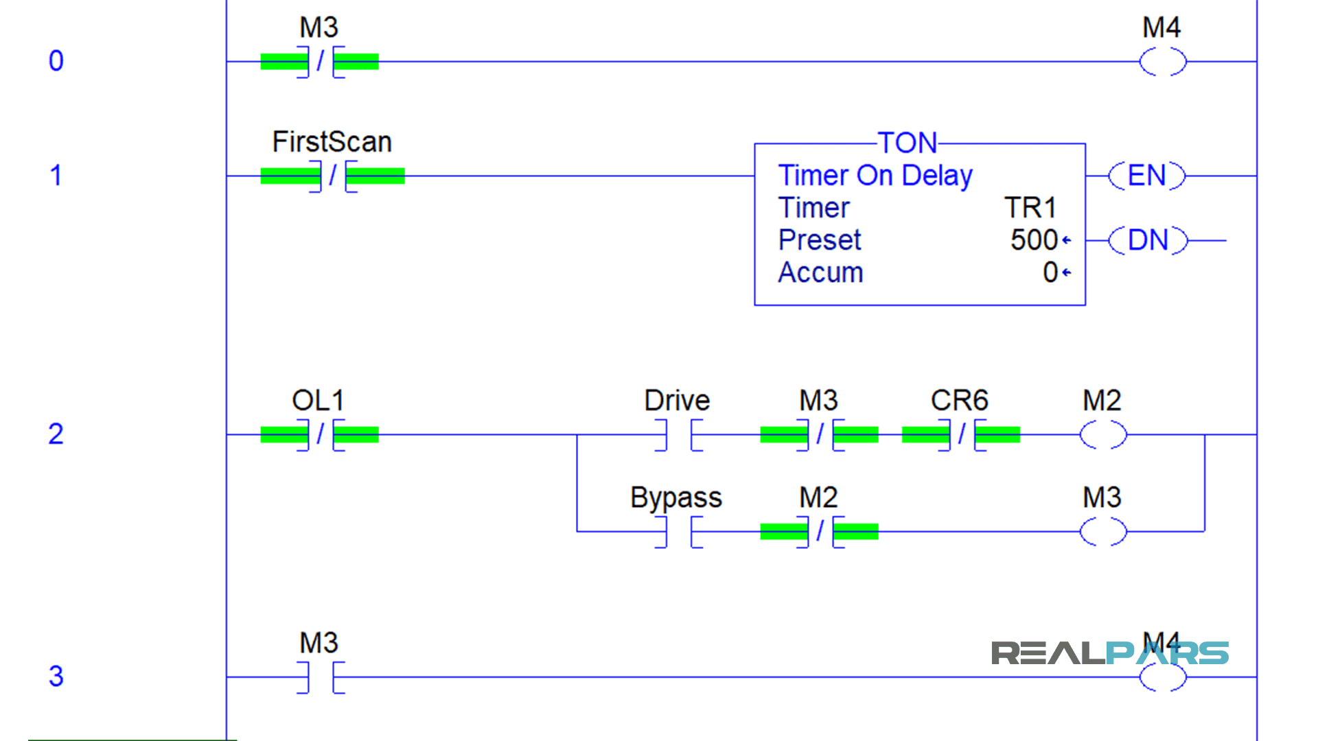
Below is an example of the logic from the example drawing I have been using, rendered in Rockwell Software’s Studio5000.
Output contacts on real-life relays are usually called normally open and normally closed.
Normally Open means that when the relay coil is not powered (”normal” for a relay) the contact is open, or not conducting. Normally closed is the opposite – when the relay coil is off, the contact is on or conducting.
So below is our software representation of a “normally open” contact.
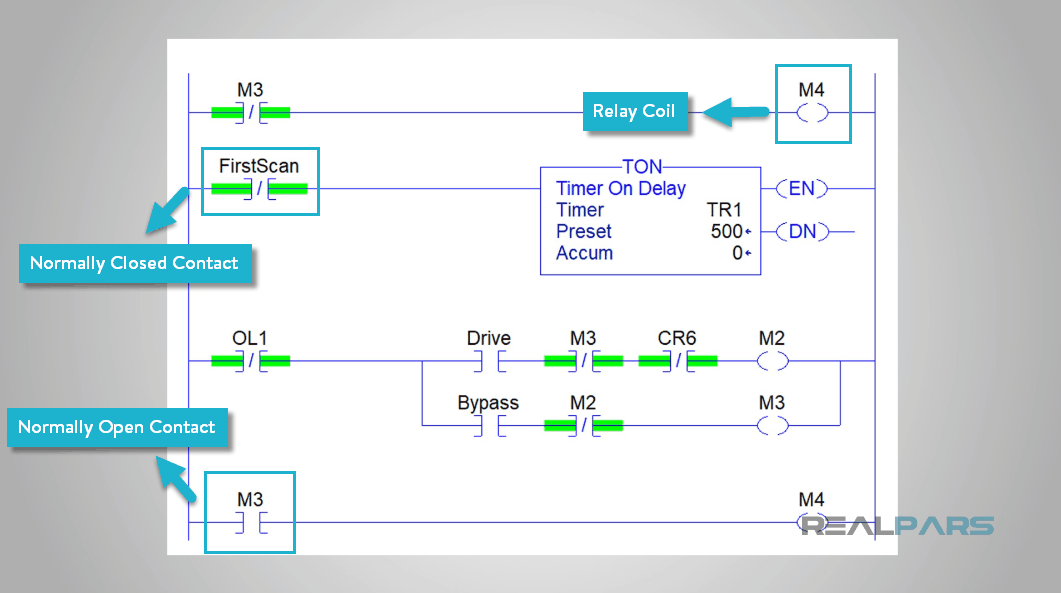
The drawing symbol and the symbol in the software are pretty much the same. Normally closed contacts are also very similar, just a representation of two separated contacts.
Finally, the relay coil – not quite a full circle like the drawing, but close enough to get the point across.
For the things we have described so far to be useful, they have to make other things happen. For instance, if the machine is ready to run and we push the auto start button, we want the machine to start continuously running until we push the auto stop button.
Here is our English sentence written in ladder logic.
Let’s take that picture apart. And look at the English with it. If the machine is ready to run – we have a contact called “ReadyToRun” – AND we push the Auto Start button – “AutoStart” contact, with the two contacts in series so that if both of them are on, then we energize the “AutoRunning” coil.
When we energize the AutoRunning coil, that also energizes the AutoRunning contact, which keeps the AutoRunning coil energized – “continuously cycling” – until we push the AutoStop button. Since that is a normally closed contact, when we push the button, it STOPS conducting, which de-energizes the coil.
The circuit we just drew in ladder logic, and the one that we could have drawn on paper, is in thousands of motor starter panels all over the world. They add stuff to it, but the basic circuit and meaning are the same – push the start button, the motor runs until you push the stop button.
Ladder Logic
Paper
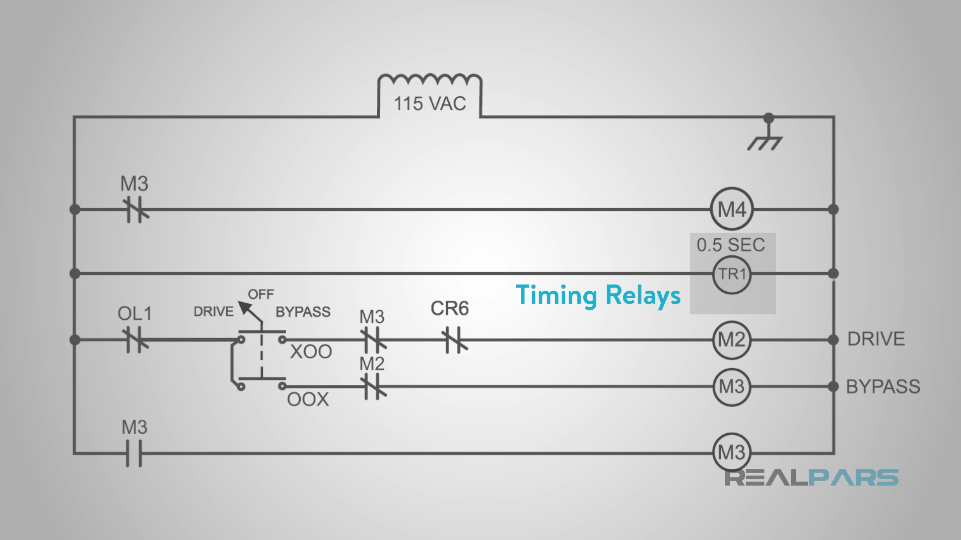
Timing relay in ladder logic
Welcome to real world ladder logic. Since the real world is more complicated than just on and off, we need some more complicated functions to deal with it. One of these was in the original drawing I started this off with, and I wanted to come back and cover it.
One of the most common functions other than on and off is a time delay, something that waits a specified period of time before turning on or off. We had one in this drawing, although its output isn’t specified. We call these timing relays when we use them in a circuit like this drawing.
In the ladder logic program, we must specify all the different needs for a timer. In our Allen Bradley ladder logic, we have an on-delay timer which is labeled TON.
The amount of time it delays is specified in milliseconds, so the half-second timer in our example becomes 500 milliseconds.
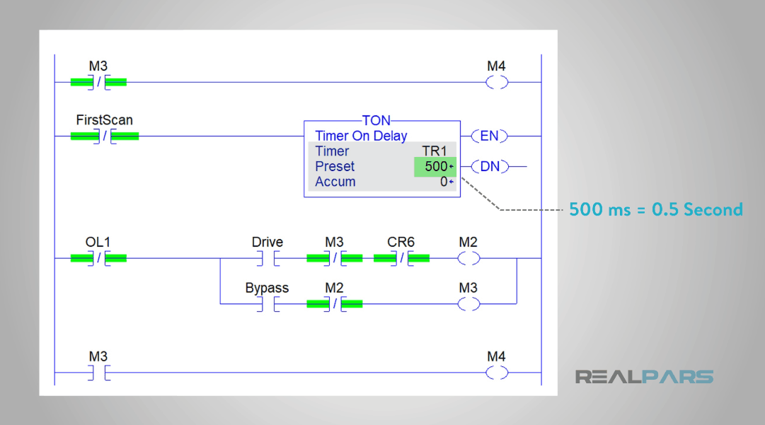
These sorts of more complex functions are what we call function blocks in ladder logic programming. The functions contained in these blocks and how they operate very between PLC manufacturers, and even within a given manufacturer’s PLCs, they may differ.
Conclusion
So, this ends our introduction to the history of ladder logic, and how it got its name. As the history of these systems recedes further in the rearview mirror, is always helpful to look back and see where we have been.
We at RealPars hope that you found it interesting, and that you will come back for more of our educational blogs.
With so much love and excitement,
The RealPars Team