

In this article, we will be talking about contactors. We will explain what a contactor is and how they work. We will also explain how to wire a contactor and the difference between a contactor and a relay.
What is a contactor?
A contactor is a device that is for making and breaking an electrical power circuit. For example, we usually use a contactor for turning on and off an electrical motor.
Why a contactor is used?
Now, why do we need to use an electrical contactor? Can't we connect the motor directly to a PLC output? Well, the short answer is no. Why? You don't want to directly connect a high-voltage electric motor to your shiny, expensive PLC. Even if the PLC output card could provide the power required for the electric motor, any electric surges on the motor's side will damage the PLC cards.
Instead, we use a contactor to connect the PLC to the motor indirectly and safely.
What do I mean by indirectly, you ask? Well, all electrical contactors have a low-voltage coil. We connect the PLC output to energize this contactor coil. This coil usually works with a 24-volt DC signal, but others are rated for different voltages.
Contactor working principle
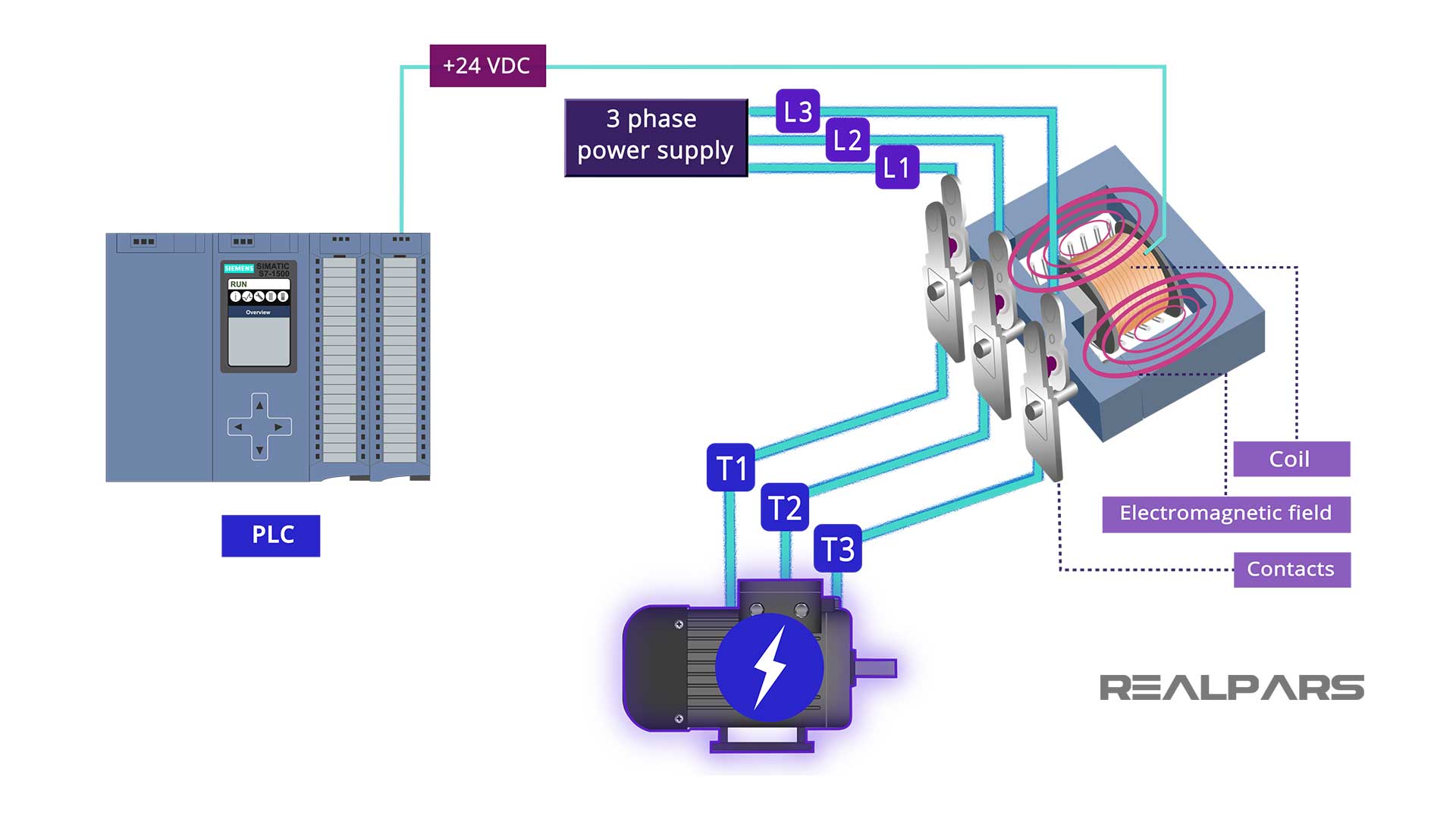
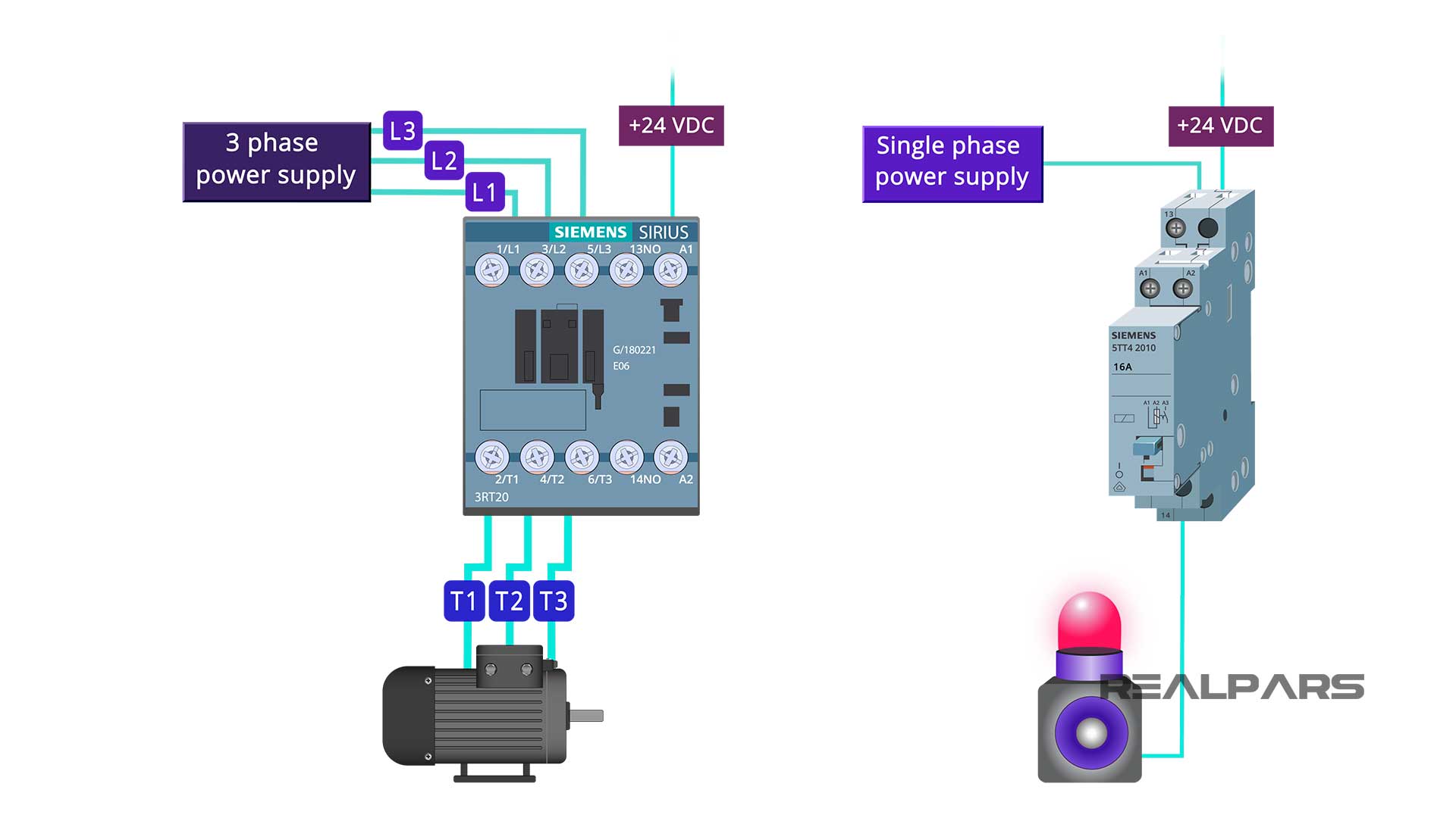
Once the contractor coil is energized by the PLC output card, an electromagnetic field will be created around it. This electromagnetic field causes the three magnetic contacts to close. Each contact is connected to the power from one of the three phases of the three-phase power supply. Once closed, the contacts complete the circuit, and three-phase power will be applied to the motor and turn it on. It looks like magic, right?
There is no physical electrical connection between the contactor coil and the contacts. The contacts will open and close via the coil's electromagnetic field.
In the off state, the coil is not energized, and the contacts are open. When a 24-volt DC signal is applied from the PLC output, the coil will energize, the contacts will close, and the motor will turn on.
This wiring configuration ensures no direct connection between the PLC and the motor. That's how you can indirectly and safely turn on and off a big high-voltage electric motor and ensure your PLC card won't be damaged. So that's why we use an electrical contractor.
By the way, you can order any PLC, contactor, or electric motor model you need from the RealPars marketplace. You can find the link to the RealPars marketplace in the video description.
Contactor vs. relay
Now that you know why we use a contactor, you may want to know how a contactor is different from a relay.
You may say… a relay also works in the same way. Can’t we use a relay instead of a contactor to turn on the motor here?
The answer to this question is No! A relay works the same way as a contactor. That means a relay also has a coil and some contact. When the coil is energized, the contacts will close. This is the same way a contactor works, right?
But here is the difference… a relay is usually used for smaller devices with lower current and voltage rates. A contactor, however, is used for bigger devices with higher current and voltage rates.
So, relays are used to turn on and off small devices and contactors are used for turning on and off bigger devices. Very simple!
Types of Contactor
As we said earlier, coils may work with different voltages for some contractors, such as 12-volt DC or 220-volt DC.
The coil can also work with AC voltage, depending on the contactor type. For example, the contactor’s coil may work with a 24, 120, or 220-volt AC power.
How to wire a contactor
Now, let’s talk a bit about the wire terminals on the contactors.
1) Coil terminals
On the front of the contactor, you’ll see two wire terminals of A1 and A2. This is where we can connect a 24-volt DC power to the coil to energize it.
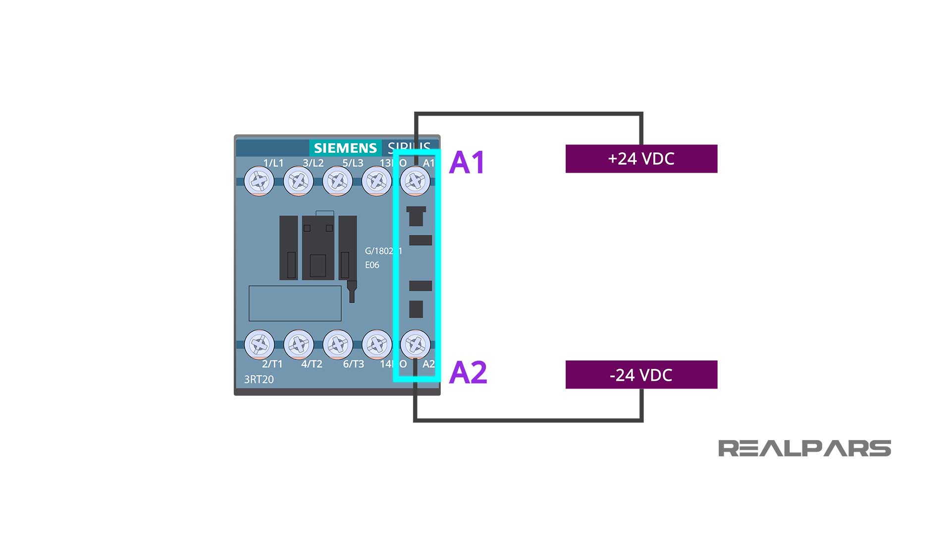
The 24-volt DC positive signal wire is connected to the A1 wire terminal, and the 24-volt DC negative signal wire is connected to the A2 wire terminal.
We’re connecting 24-volt DC power to these terminals because the coil works with 24-volt DC power for this electrical contactor.
2) Contacts terminals
We have six other wire terminals on the contactor's other side. The wire terminals on the top are labelled from left to right with L1, L2, and L3, and the wire terminals on the bottom are labelled from left to right with T1, T2, and T3.
The L1, L2, and L3 terminals are connected to the line or the power supply wires. The T1, T2, and T3 terminals are where the device or load wires are connected.
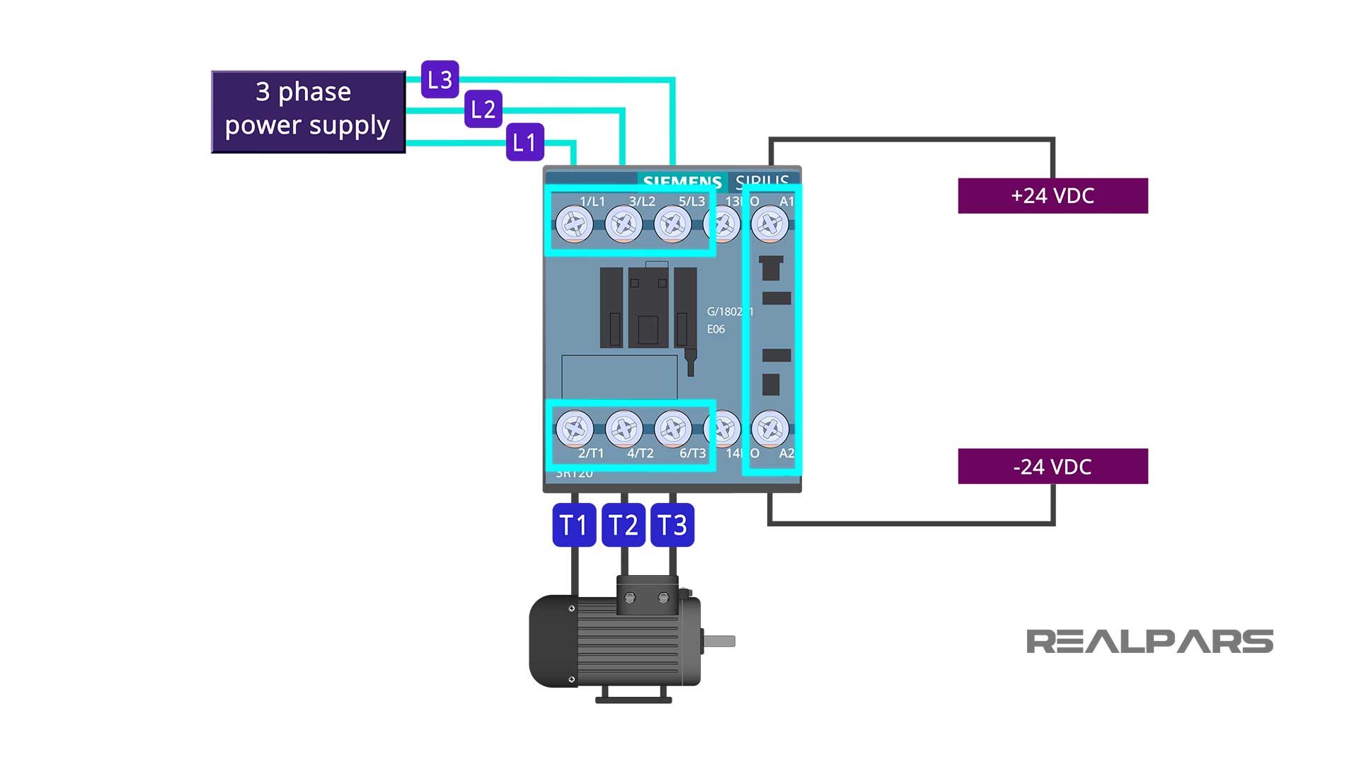
When the coil is energized, the L1 contact connects to the T1 contact, the L2 contact connects to the T2 contact, and the L3 contact connects to the T3 contact.
The contactor contacts are normally open; therefore, the device will be off with the coil de-energized. When the coil is energized, the device will power on..
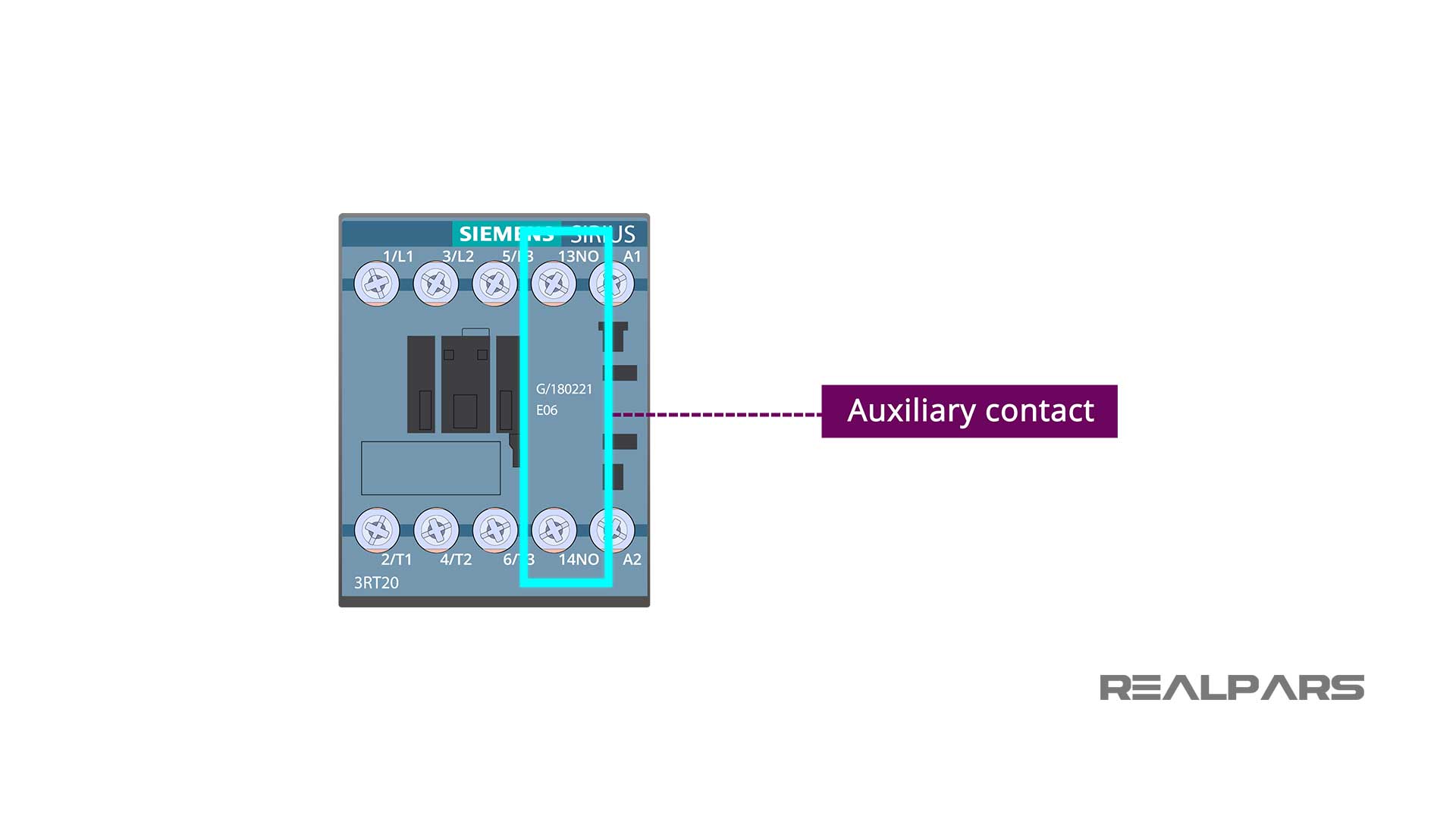
3) Auxiliary or feedback contact terminals
As you can see, we have another set of wire terminals on the front end labeled as NO or normally open. This is a simple normally open contact referred to as an auxiliary contact or a feedback contact.
How does a feedback contact work?
This contact is used to send a signal to the PLC input about the contactor’s health. What do we mean by that? The way that this contact works is that when the coil is energized and these three main contacts are closed, this feedback contact will be closed as well and send a signal to the PLC input.
However, when the contactor is broken and energizing the coil will not result in these three main contacts being closed, the feedback contact will not be closed either and no signal will be sent to the PLC input.
This way, there is a way for us to be notified if the contactor is broken.
We have discussed this more in our level 2 PLC programming course and there is a sample PLC program that shows why we always need to use a feedback contact and how to use that contact in the PLC program to get notified when the contactor is broken.
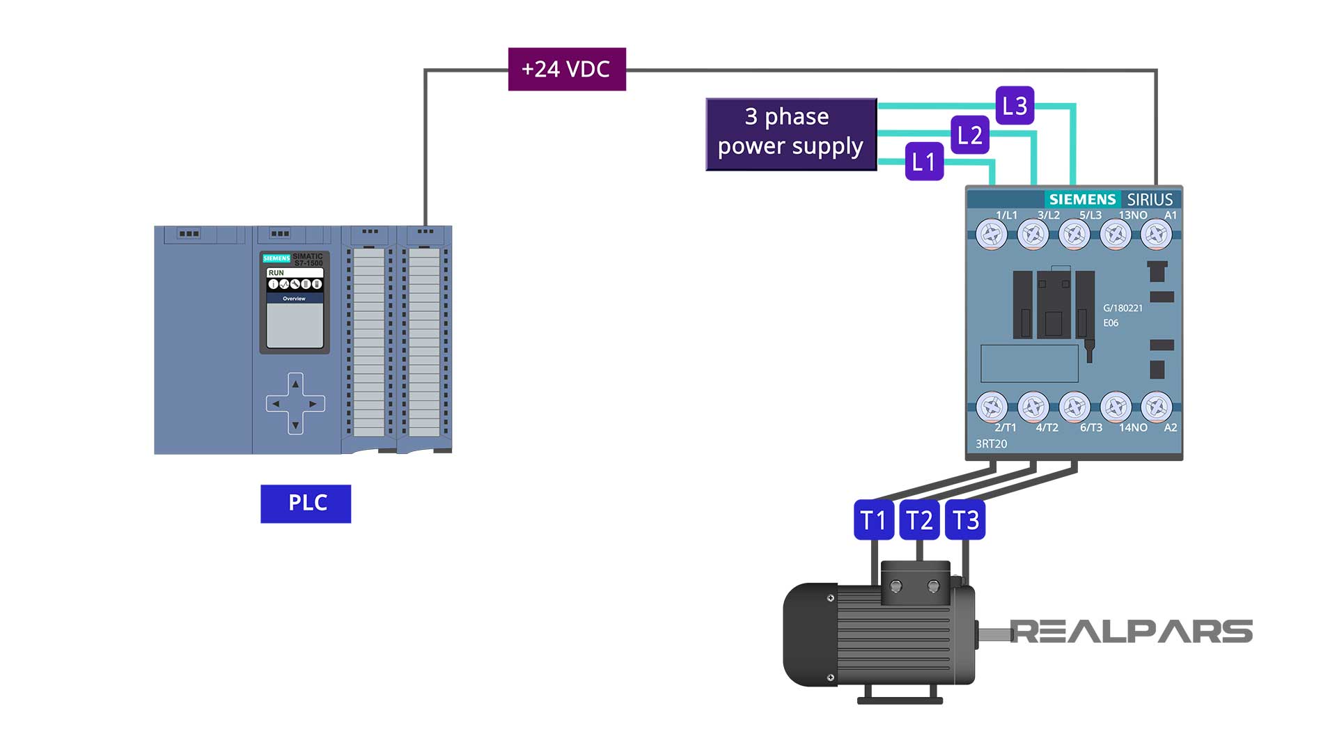
How to wire a contactor to the PLC and motor
Ok so, to control a motor using a PLC through a contactor, you need to connect the PLC output to the coil to be able to energize and de-energize it.
You connect a 3-phase power supply to L1, L2, and L3 from one end, and then from the other end, you connect T1, T2, and T3 to the motor.
To be notified when the contactor is broken, you need to connect this auxiliary or feedback contact to the PLC input.
You also need a start and stop switch to be connected to the PLC input. This way, when you press the start switch, the coil will be energized, the contacts will be closed and the motor will be turned on. When this happens, the feedback contact will be closed as well and a signal will be sent to the PLC input, telling us that the contactor is working properly.
When you press the stop switch, the coil will be de-energized, the contact will open and the motor will turn off.
Summary
In summary, in this article, you learned that
- We use an electrical contactor to turn on and off heavy and high-voltage electrical devices such as motors, fans, pumps, etc.
- The reason that we use a contactor is to control these heavy high voltage electrical devices indirectly and safely via a PLC and not to connect the PLC directly to these output devices.
- The main difference between a contactor and a relay is that a contactor is used for turning on and off heavy high-voltage devices, but a relay is usually used to turn on and off smaller low-voltage devices.
We hope that you now clearly understand what a contactor is and how it works.
Got a friend, client, or colleague who could use some of this information? Please share this article.