

This article will discuss the often forgotten, behind-the-scenes workhorse – the 24-volt DC Power Supply.
We will talk about what can go wrong with 24VDC supplies, we’ll discuss how power supply issues can impact digital sensor connections, and impact analog sensor loops.
We will also discuss calculating power supply requirements and diagnosing power-related Issues in the field.
24VDC power supply issues
Power supply ripple
Let’s start with what can go wrong with 24VDC power supplies.
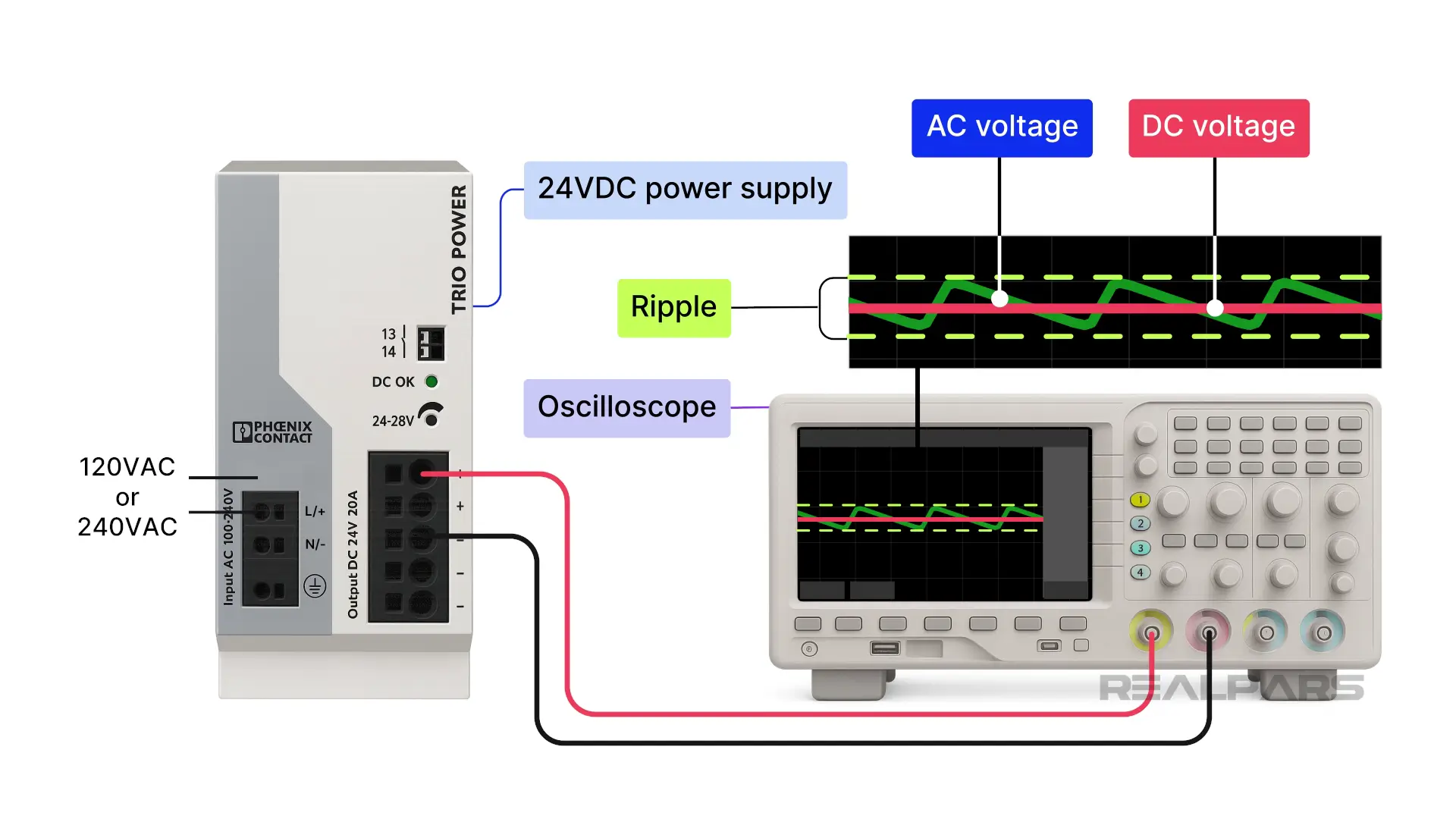
Power supply ripple is bad news. Ripple is an unwanted AC voltage sitting on top of the power supply's DC voltage. It is a byproduct of the rectification and filtering of the AC input voltage, as the AC mains feed most power supplies.
Many devices and circuits are unhappy with ripple, resulting in erroneous signals.
Overload
An increase in load often causes an increase in ripple in older-style power supplies.
Overload is also bad. If the total current demand exceeds the power supply’s rated output, problems ensue. What causes overloads? One cause is that too many devices are connected to the power supply.
Unexpected excessive current draw by any load will also cause an overload.
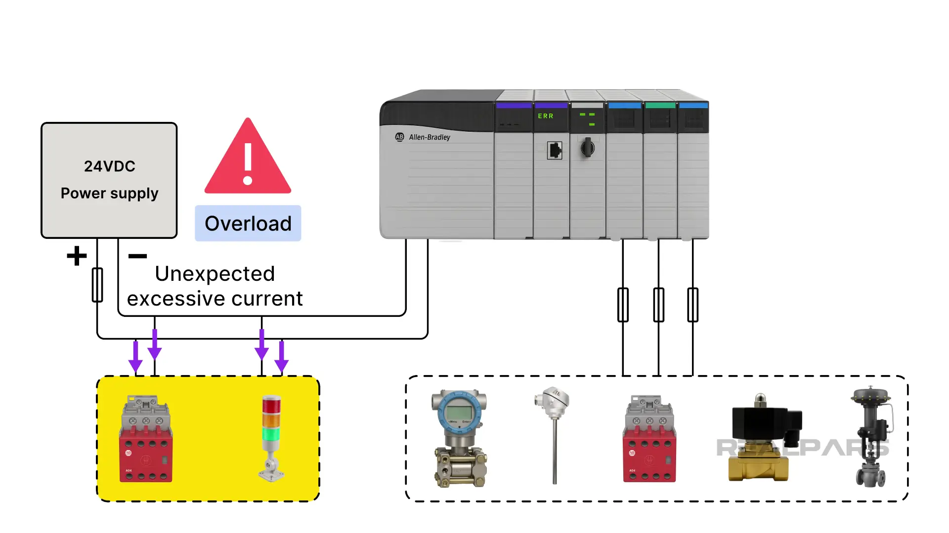
Some power supplies will shut down, while others might go into a current limit mode. Fusing load circuits will go a long way in preventing overloads. We’ll show you an example of fused loads later.
Unregulated power supply
What if the power supply voltage output is not stable? Are instrument power supplies regulated or unregulated? Theoretically, an instrument power supply used in a 2-wire loop does not need to be regulated because the transmitter will compensate for voltage fluctuations.
Keep in mind that 2-wire loops may not be the only circuits using the 24VDC power supply. Regulated power supplies ensure low ripple and exceptional noise reduction, which are essential in today’s systems. For example, loops with HART communication cannot easily tolerate noise.
Power supplies like the Phoenix Contact TRIO-PS are used because of their nominal regulated output voltage of 24vdc +/- 1%.
Voltage drops
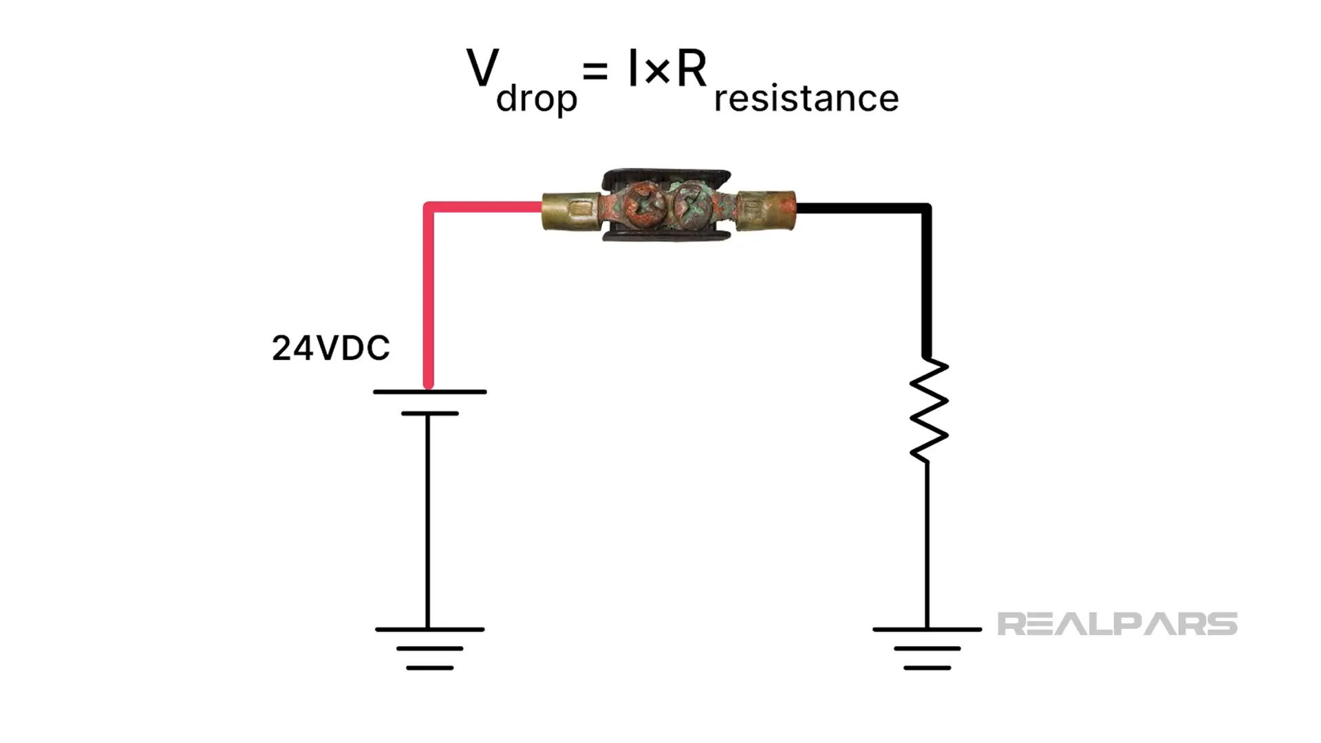
Voltage drops are an issue, but not necessarily a power supply fault. A voltage drop occurs when the voltage at the load is lower than the voltage at the source.
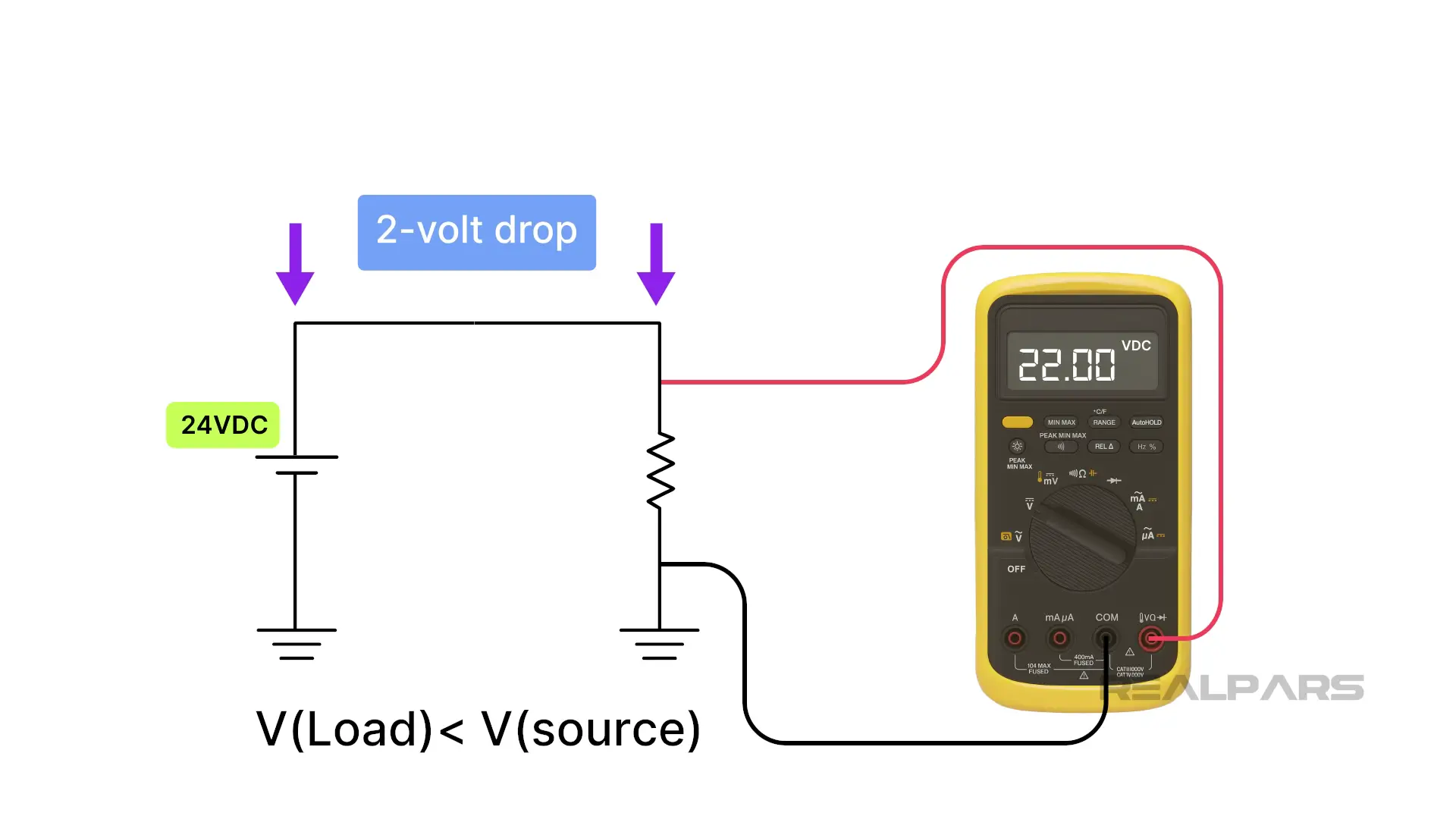
Ohm's Law can be used to explain voltage drops. As we know, V= IXR.
Let’s demonstrate. The voltage drop is equal to the current times the wire resistance. A voltage drop will result if the wire is too long and/or the wire gauge is too small. Terminal corrosion causing unwanted resistances is nasty and will also create voltage drops.
A voltage drop in a 2-wire loop is not an issue because the current is the same at all points, and the transmitter manages the amperage. But, as we said earlier, not all circuits are 2-wire loops. Voltage drops in other circuits can cause significant signal and reading errors.
Impact of power supply issues
Let’s talk about the impact of 24VDC power supply issues on PLC analog input circuits.
Temperature circuits with Resistance Temperature Detectors are susceptible to power supply issues. Older style RTD transmitters utilize circuits requiring precise voltage excitation. Any excitation voltage variance causes signal errors. Noisy power supplies are problematic on long RTD cables.
We talked briefly about how 2-wire loops are affected by power supply issues. What about 4-wire loops with separate power supply lines and current signal lines?
Generally speaking, today’s 4-wire transmitters are quite happy with a wide range of supply voltages and therefore not susceptible to unstable supplies. However, ripple and noise are problematic and can cause erroneous signals.
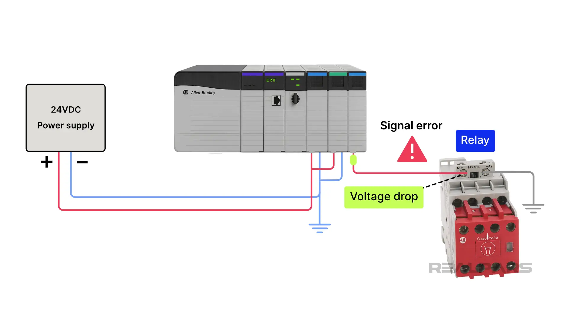
Let’s discuss the impact of 24VDC power supply issues on PLC digital input circuits.
PLC Input modules tolerate power supply voltage variations up to a certain point. For example, the AB 1756-IB16 input module has an operating voltage range of 10VDC to 31.2VDC. However, the on-state voltage minimum is 10VDC.
Consider what might happen if the voltage applied to a digital input is 8.3VDC, caused by a temporarily overloaded power supply or a voltage drop somewhere. The outcome is unpredictable, and intermittent behaviour may result.
Determining +24Vdc PS requirements
How do you determine the requirements for a +24VDC power supply, or how do you know if you can safely add another circuit? It’s important to determine the total current draw for all devices when each device is supplied by it and is drawing maximum current, then add 20% for good measure.
How do you get all of this information? You need device data sheets, system wiring drawings and loop diagrams.
24VDC power supply example
Let’s go through an example.
Our example system has at least one 24VDC power supply, and we’re pretty sure it’s in the PLC cabinet.
If we want to, we can physically locate it by looking for fuses, circuit breakers, and a 24-volt terminal block in the PLC cabinet. We might even find a redundant power supply close by.
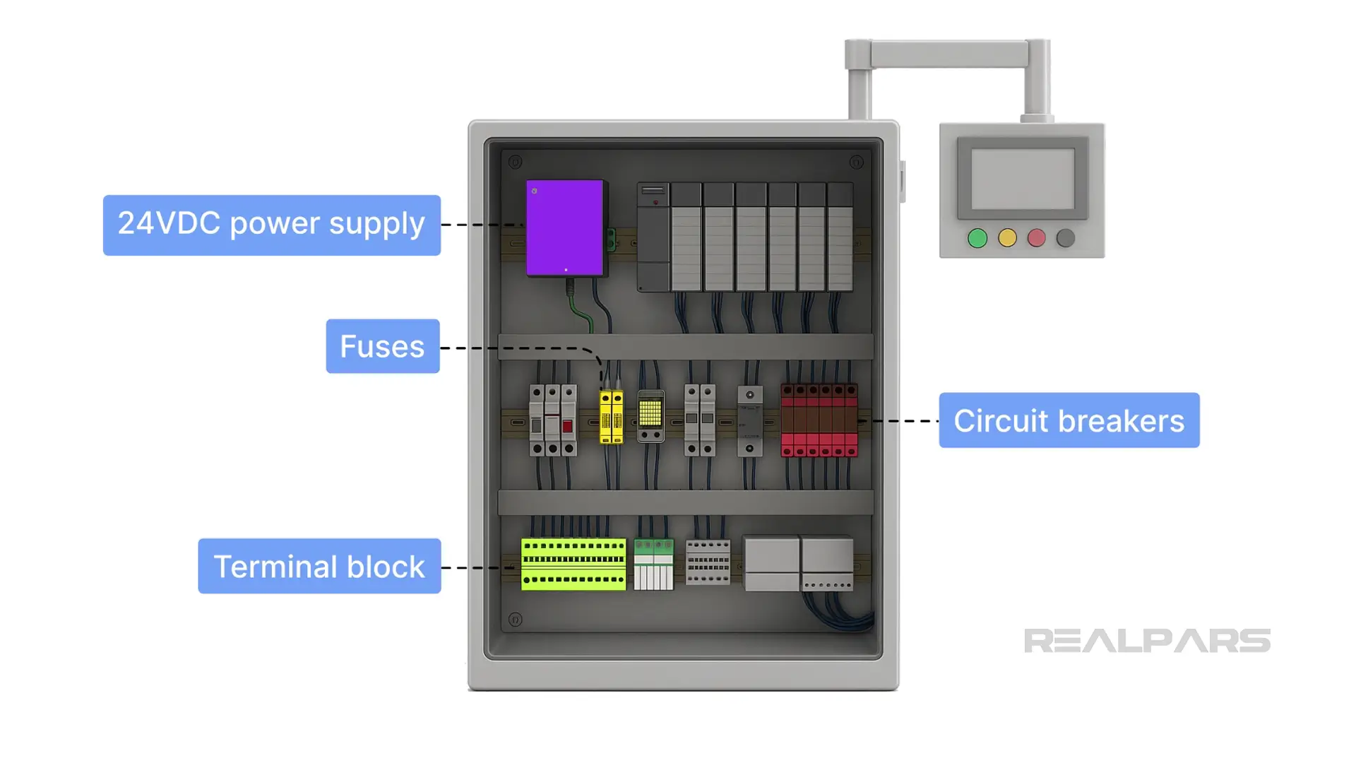
We know that many devices and circuits require power, such as field devices, relays, solenoids, I/O modules, and perhaps HMI panels.
We have a good idea of what devices and circuits the 24-volt DC power supply is powering, but we cannot be sure without more evidence.
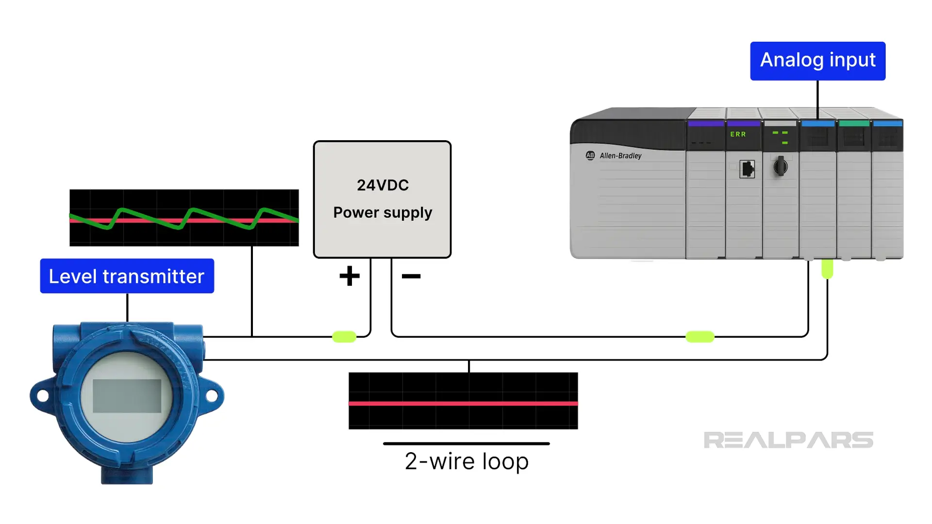
Digging into our documentation, we find a Level loop diagram with Level Transmitter LT-YA255 that shows a +24vdc connection through a 0.5a fuse on TB-107 terminal number 40.
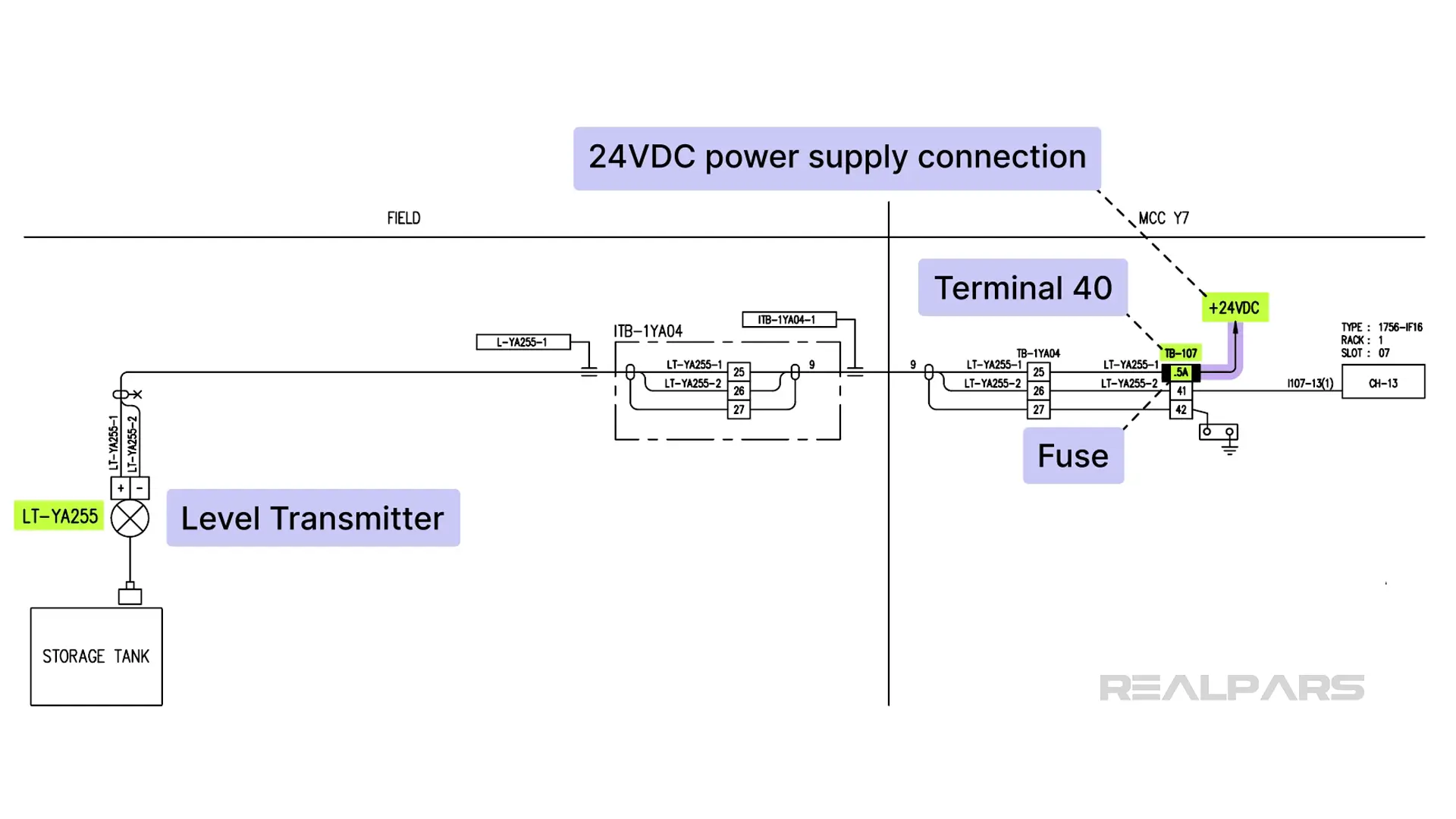
We can condense and redraw this level loop into its equivalent 2-wire circuit.
We can assume other loads are connected to this 24VDC power supply as it likely powers more 2-wire loops, and possibly other circuits. There may be more power supplies, too.
Where do we look for other possible loads connected to this power supply?
Let’s see if we can find TB107 on another drawing.
Upon further searching, we track down the wiring diagram for a 1756-IF16 analog input module, which shows us two more 2-wire loops powered by the same +24vdc power supply connected at TB107 terminal number 1.
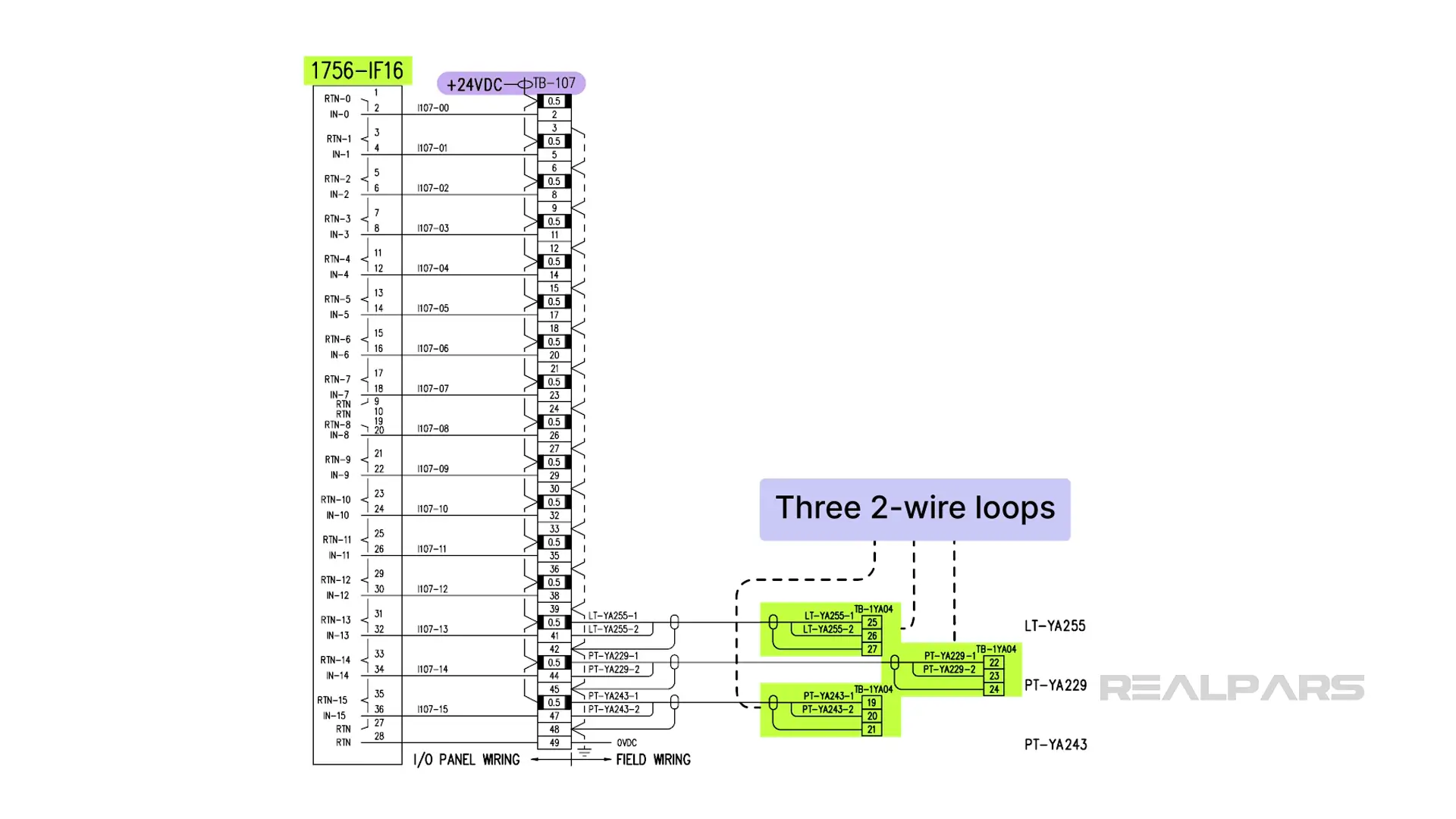
OK, so far we’ve discovered three devices powered by this +24VDC power supply.
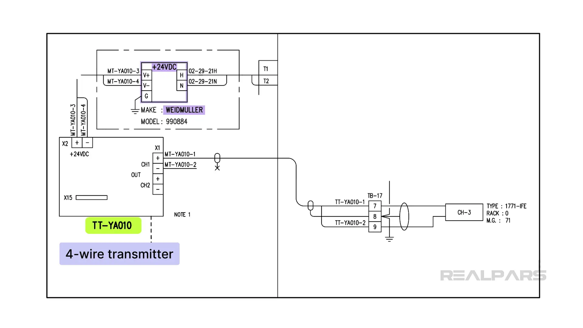
Digging further into the documentation, we find a 4-wire transmitter TT-YA010 powered by a separate Weidmuller +24VDC power supply.
Further sleuthing and digging will provide you with what you need to decide the requirements for the power supply under consideration.
Diagnosing power-related issues
We’ll end this article with a short discussion on diagnosing Power-Related Issues.
Erratic equipment behavior, weird signals, and unexplained glitches can be symptoms of power supply issues.
Measuring ripple
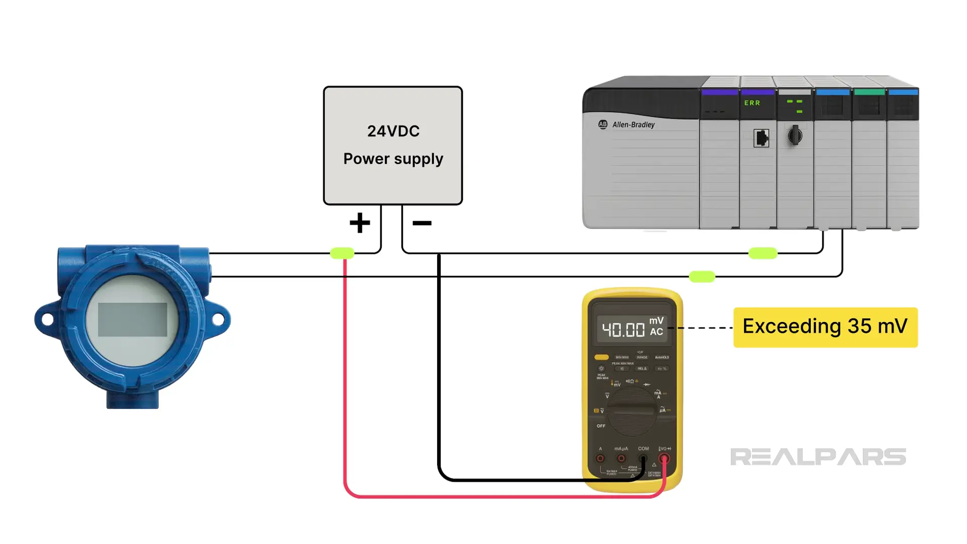
An oscilloscope is the best tool for measuring ripple, but it can also be done with a Digital Multimeter (DMM). The Phoenix Contact TRIO-PS we mentioned states a residual ripple value of less than 100 mVpp .
Because a ripple voltage looks more like a sawtooth than a sine wave, the DMM may have a problem because it measures RMS voltages.
Nevertheless, the DMM set can be connected to measure AC volts across the 24VDC output terminals. Any reading exceeding 35 mV RMS indicates the power supply's specifications are breached.
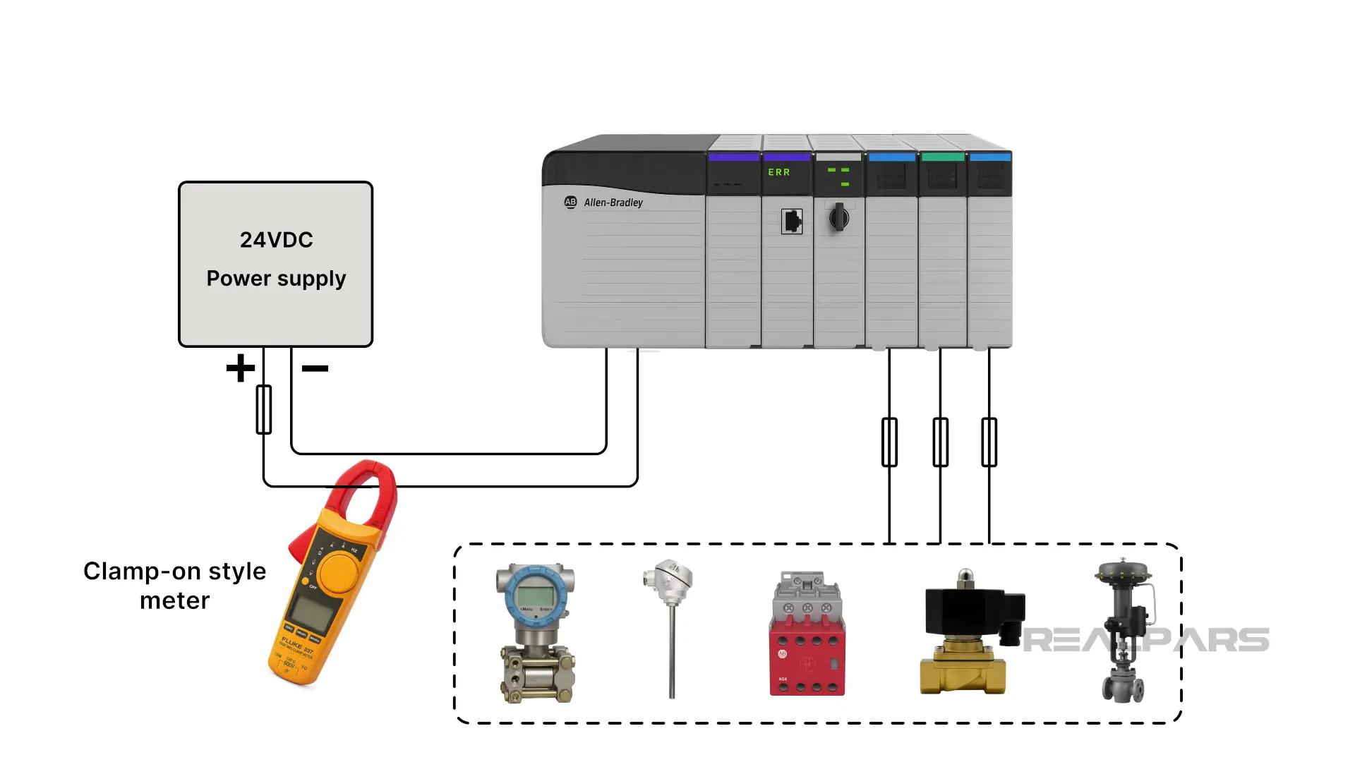
Detecting overload
Measuring the power supply current to detect an overload condition is a simple solution, but it is not very practical unless you have a clamp-on style meter. Conventional ammeters are placed in series, requiring all loads to be temporarily disconnected.
Detecting voltage drops
Detecting voltage drops requires measuring the voltage at the source, then at the load, and subtracting the two values.
Visual inspection can detect loose or corroded connections and terminals.
Thermal imaging devices can also be used if available.
If you're a plant manager looking to train your team, visit realpars.com/business. Enter your contact details, and our team will get in touch shortly to explore how we can support your team's growth.