

Welcome to Part 5 and the final lesson of How to control a VFD with a PLC. As a prerequisite, please take a look at lessons 1 through 4. We have created this series of lessons discussing the steps to configure and program communication between a Rockwell ControlLogix PLC and a Siemens VFD using Siemens Starter software.
In Part 5, this article, we will pick up where we left off in Part 4 to complete the VFD configuration and the communication path between the gateway and the Rockwell ControlLogix processor. Learn about configuring communication data in Siemens Starter Software below.
In the previous part, I left off right after completing the motor and its nameplate data configuration in the Starter software.
Let’s pick up from the last step of the motor configuration where we had configured the Important parameters of the motor.
In the Important parameters display, as you can see, I set some of important parameters according to the motor’s datasheet.
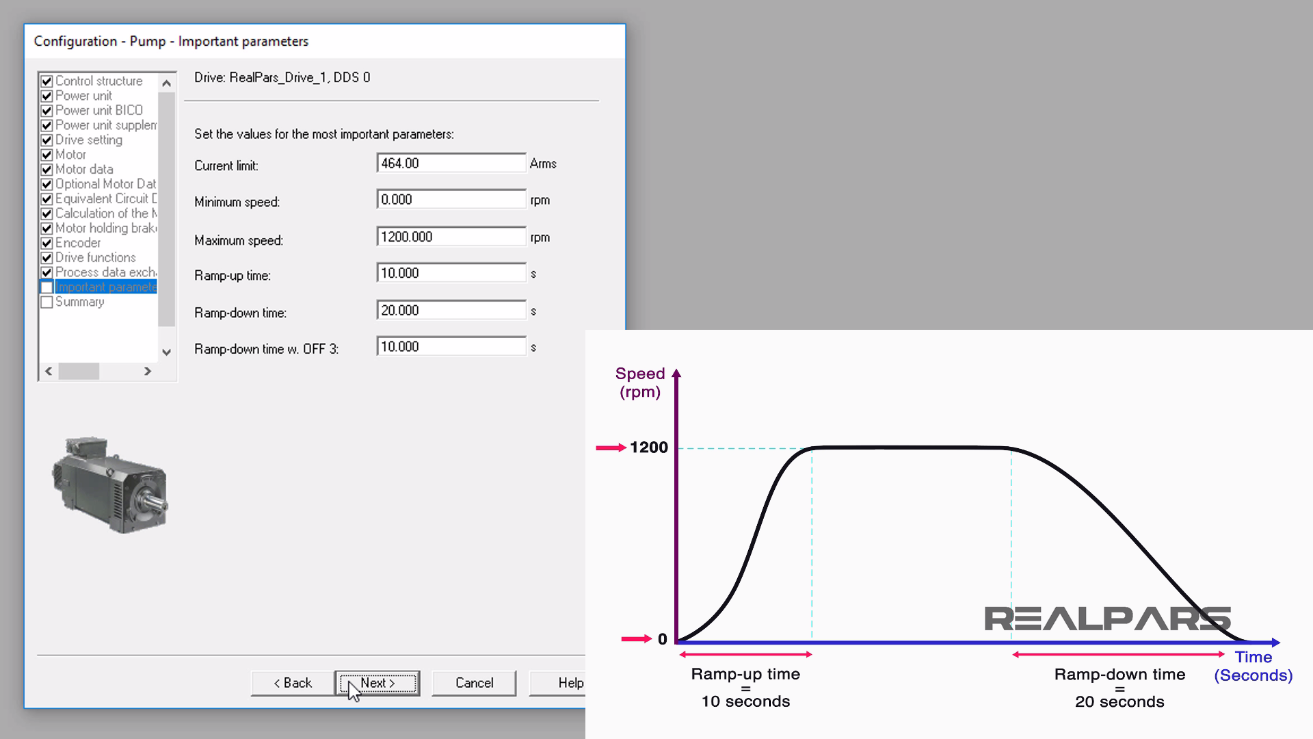
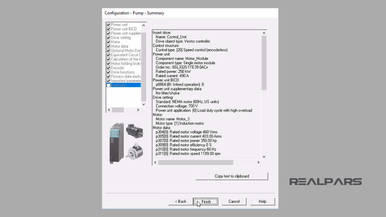
I continued by selecting the Next button and the Pump Configuration Summary display appeared.
I selected the Finish button to continue.
Configuring the Communication Data in the Siemens VFD Using SINAMICS STARTER Software
Over the next few steps, we will be configuring the parameters we used in the Part 1 and Part 2 to allow the VFD to communicate with the ControlLogix 5000 PLC.
You can learn more about the VFD parameters and their usage via the “SINAMICS S120/S150” manual.
Under the Drives folder, I expand the RealPars_Drive_1.
Then I double click on Communication item.
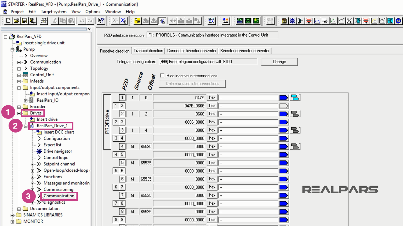
I will select the Receive direction tab.
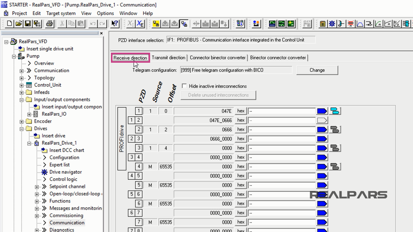
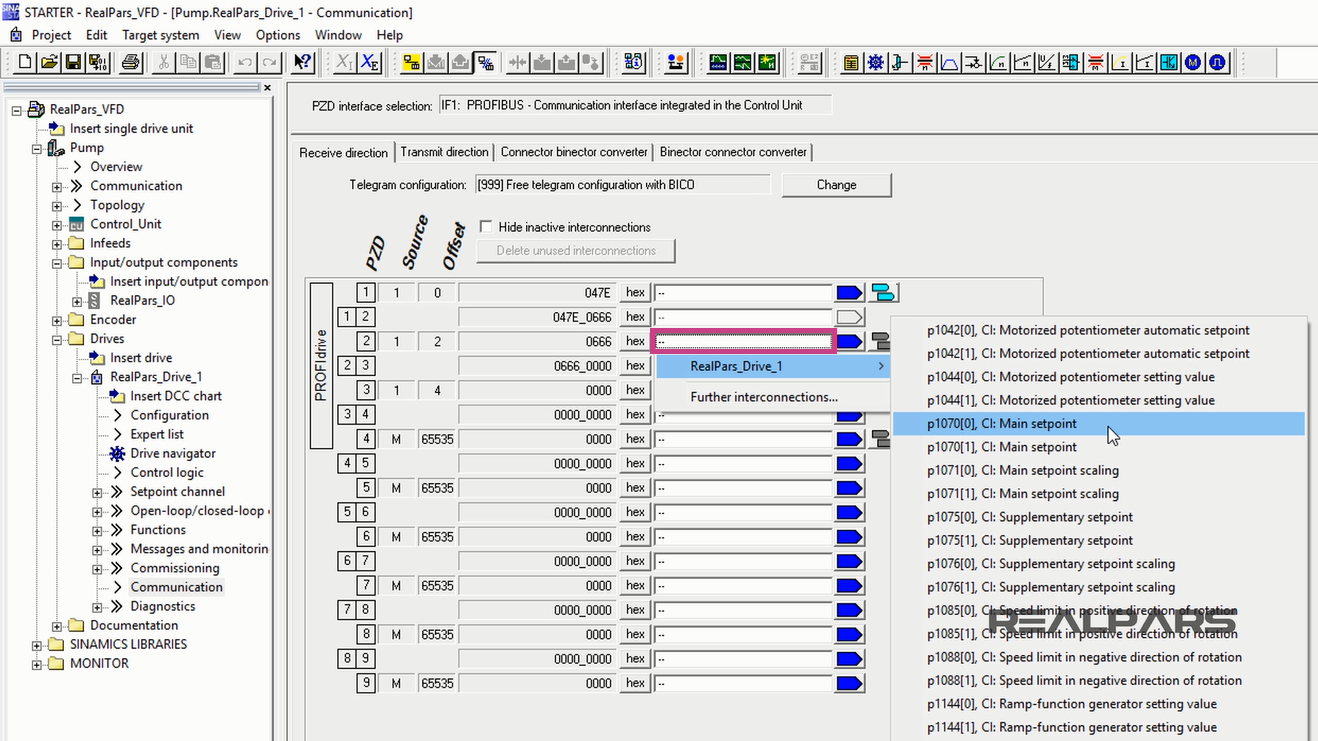
Within the Receive direction tab I will click into the PZD 2 white area, next to the hex box.
Then I open the RealPars_Drive_1 menu to select p1070[0], the Main Setpoint.
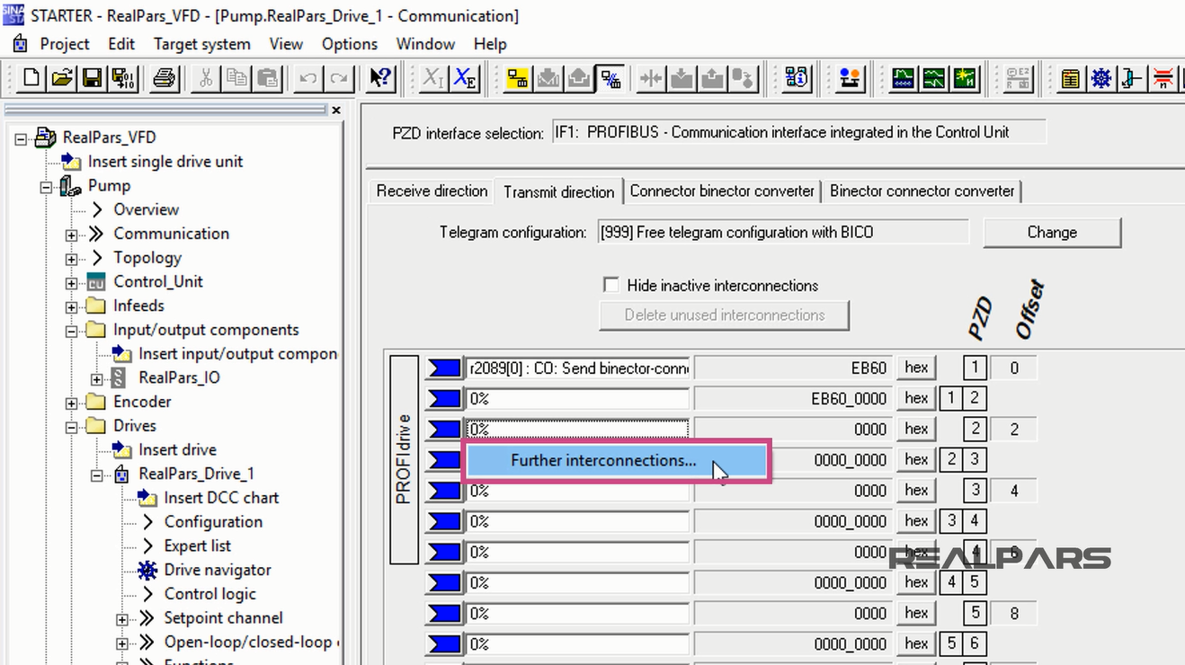
Next, under the Transmit direction tab, I will enter a few more parameters.
First I click into the PZD 1.
Then I locate r2089[0], the send binector-connector convertor status word, Status word 1 and select it by clicking on it.
If you open the SINAMICS S120/S150 Parameter Manual and search for the r2089[0], you will find out where the ZSW word naming derives from.
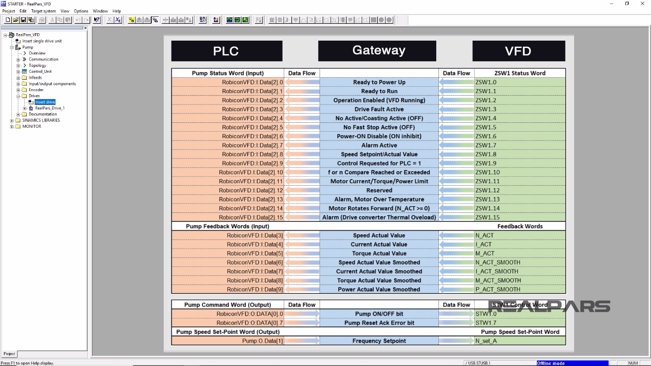
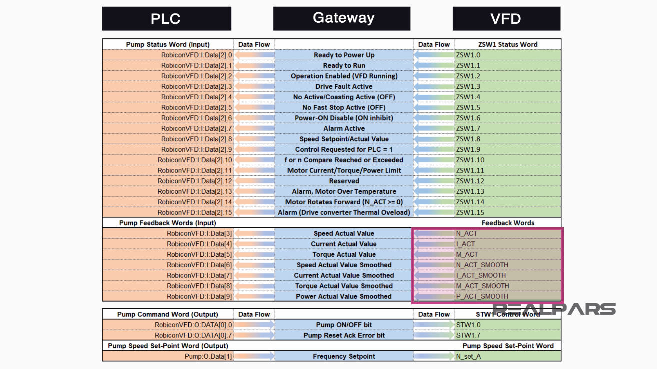
From previous parts of this article series, you can remember the ZSW1 status words in the spreadsheet, which were sent from the Siemens VFD toward the Rockwell PLC via the HMS Anybus Gateway.

I will complete the remaining entries here in the Transmit direction Tab.
I click into the PZD 2 white area.
Then I select Further interconnections.
I locate r63[0], the Actual Speed Value, Unsmoothed.
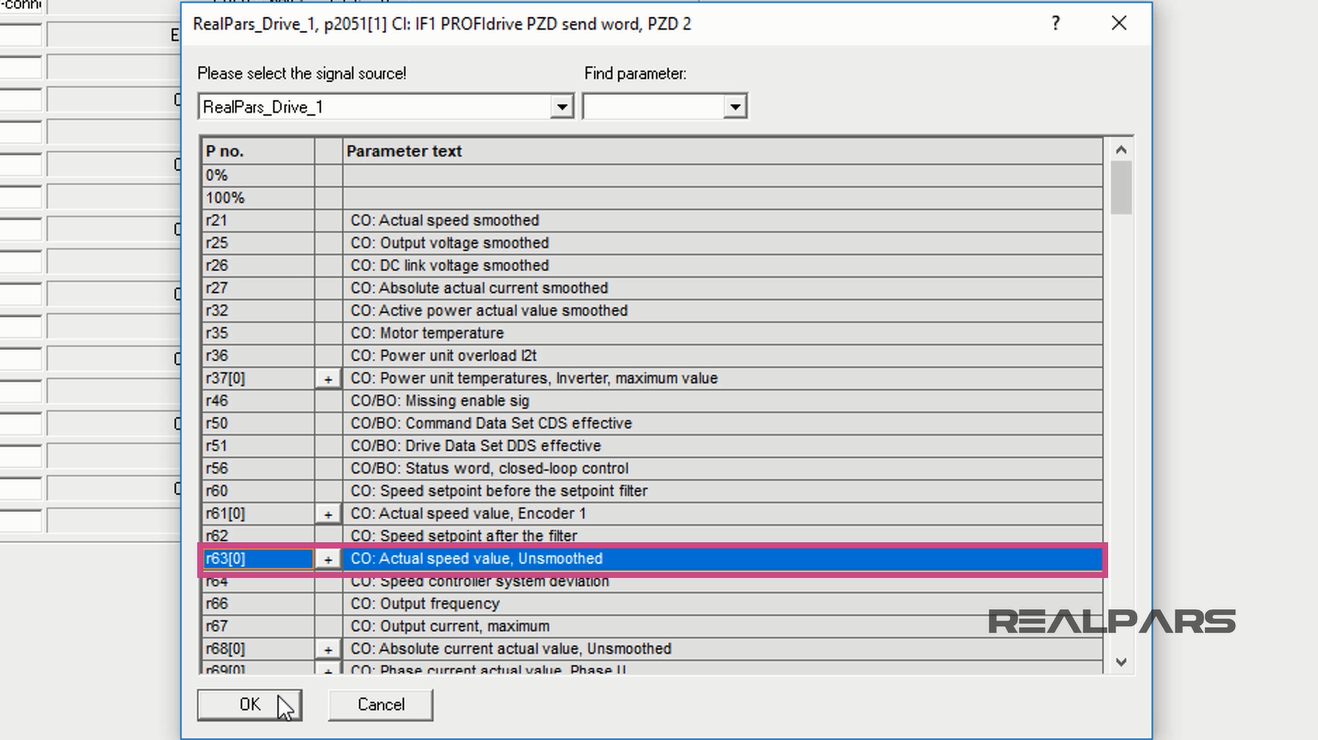
This entry represents the N_ACT communication tag from the spreadsheet.
Then I hit OK.
I click into the PZD 3.
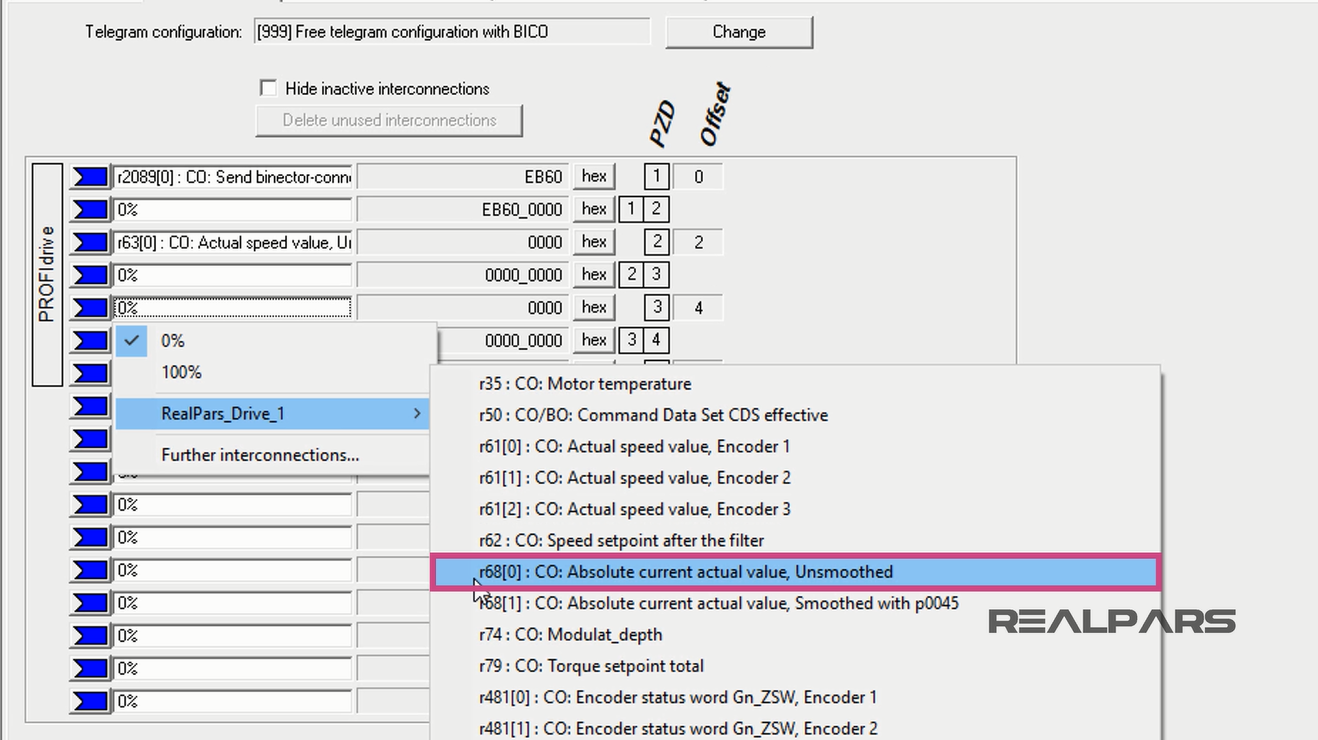
I open the RealPars_Drive_1 menu to locate r68[0], the Absolute Current Actual Value, Unsmoothed.
This is the I_ACT tag from the spreadsheet. I then select it by clicking on it.
For the next word, I click into the PZD 4.
Then I select Further interconnections.
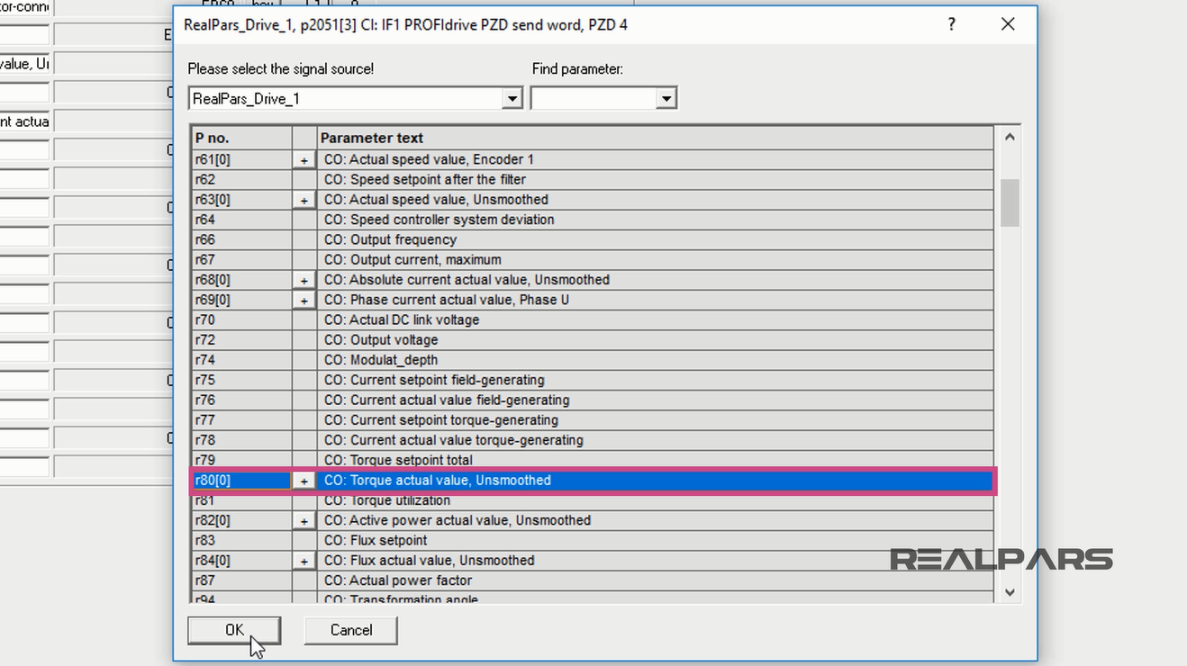
I scroll down until I select r80[0], the Torque Actual Value, Unsmoothed.
It is the M_ACT tag from the spreadsheet.
To continue, I hit OK.
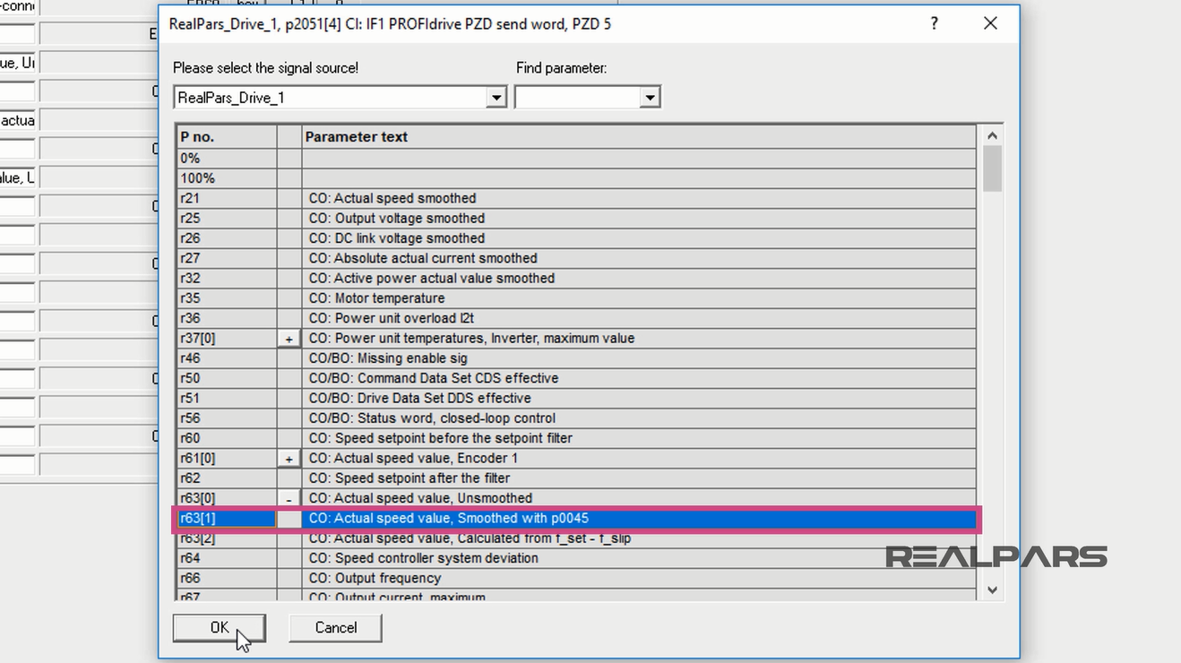
I click into the PZD 5. Then I select Further Interconnections.
I find and expand r63[0]. Then I select r63[1], the Actual Speed Value, Smoothed with p0045”.
This parameter represents the N_ACT_SMOOTH communication tag from the list.
To continue I press OK.
I click into the PZD 6.
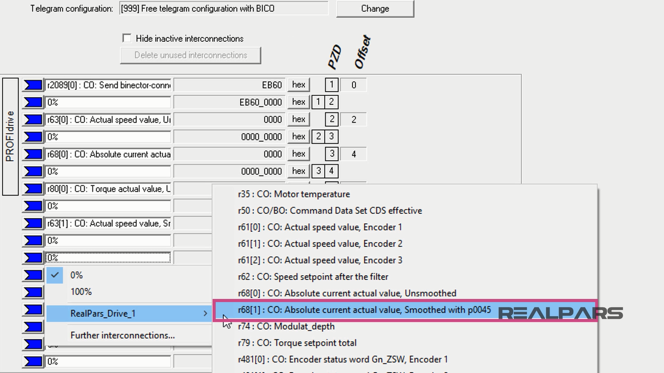
Then I open the Realpars_Drive_1 menu to locate r68[1], the Absolute Current Actual Value, Smoothed with p0045.
This word represents the I_ACT_SMOOTH from the spreadsheet tags. I select it by clicking on it.
I click into the PZD 7. Then I select Further Interconnections.
I scroll down to find and expand r80[0]. Then I select r80[1], the Torque Actual Value, Smoothed with p0045.
This entry represents the M_ACT_SMOOTH communication tag name.
To continue I hit OK.

Finally, for the last parameter, I click into the PZD 8. Then I select Further interconnections.
I scroll down to find and expand r82[0].
Then I select r82[1], the Active Power Actual Value, Smoothed with p0045.
This entry represents the P_ACT_SMOOTH communication tag.
To continue I press OK.

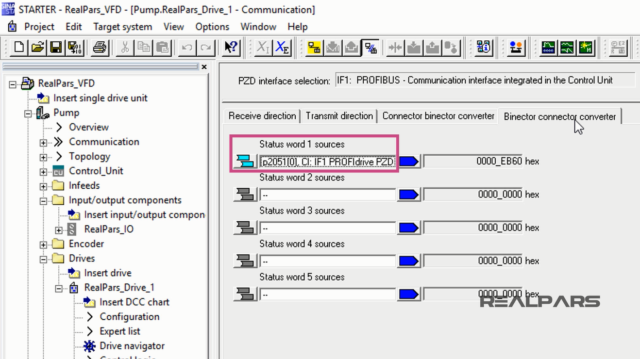
Now on the final tab, Binector connector converter, you can see that the first slot, Status word 1 sources, Automatically changes to p2051[0].
This concludes the last article of this series, ControlLogix PLC and Siemens VFD Communication structure and programming using Starter software.
I hope you have enjoyed learning what will support you in your upcoming project.
If you would like to get additional training on a similar subject, please let us know in the comment section.
Please check back with us soon for more automation control topics.
Got a friend, client, or colleague who could use some of this information? Please share this article.
The RealPars Team
How to Control a VFD with a PLC – Part 1
How to Control a VFD with a PLC – Part 2
How to Control a VFD with a PLC – Part 3
How to Control a VFD with a PLC – Part 4