
In this article, we will explain what PLCPART.tp is and why it is important.
Due to the restrictions of PalletPro, you will not be able to run this program on your PC. This is because PalletPro takes over PalletTool, and there is no way to break this link. However, you can export this teach pendant program to HandlingPro and run it like a regular teach pendant.
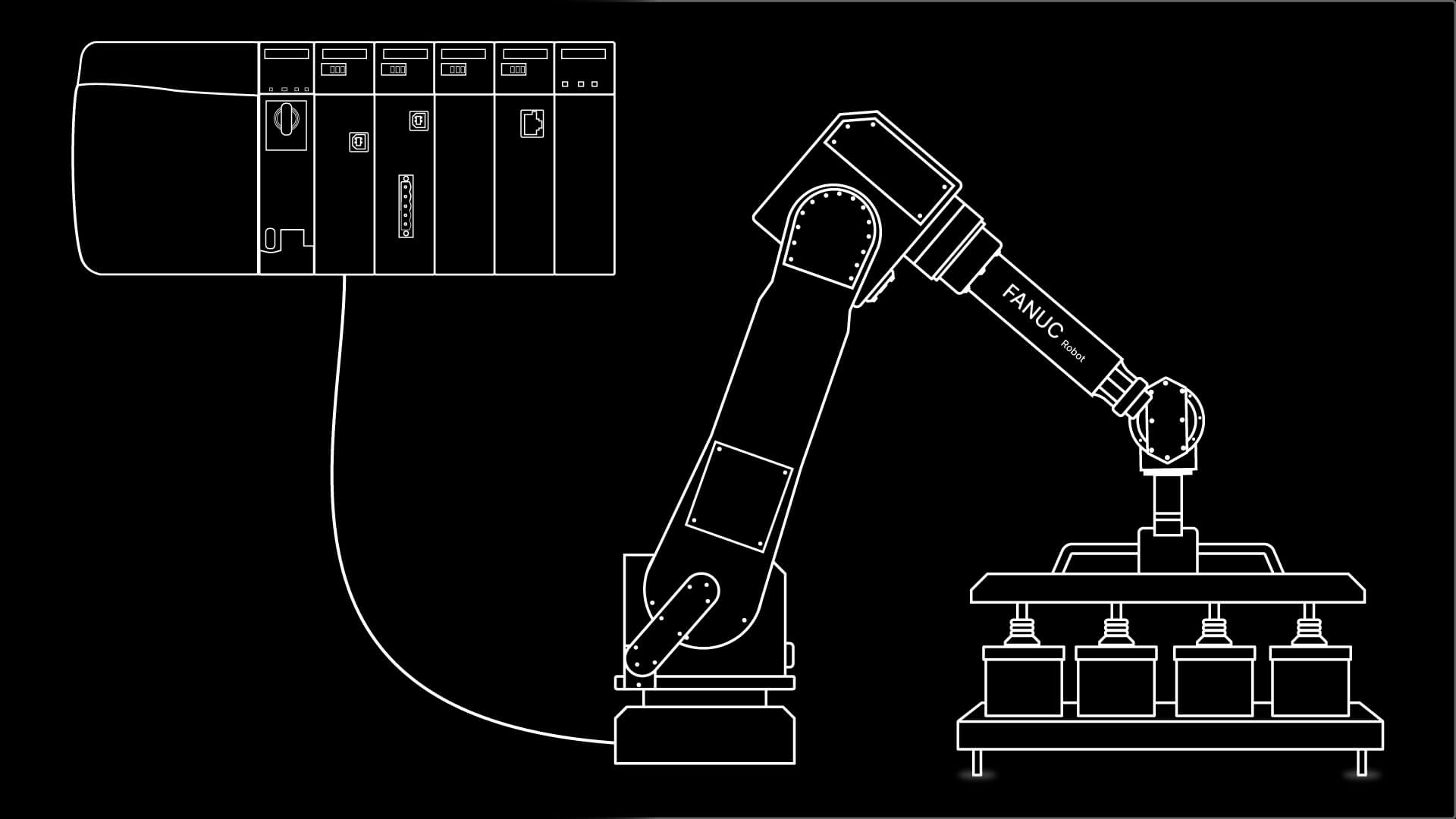
You may connect a PLC to HandlingPro. See the FANUC Robot Training course series for step-by-step tutorials on how to set all of this up.
PLCPART.tp is a program that is used to change the UnitLoad data. Simply put, this is what the robot is going to run. Another way of looking at it is that this program is a communication program to talk to the PLC.
For those who prefer video, the full explanation is available below. Otherwise, you can continue reading the article.
Explanation of terms
Before we start looking at the program, I want to explain a few terms. This should help us understand the program by knowing the jargon.
Total Cycles: PLCPART.tp sets the number of cycles, which is PalletTool’s way of saying how many infeed and pallet stations there are in a cell.
Load Type: In PalletTool, there are only two options. Regular pallets using the ULxxx in their name will be set to a value of 0. Mixed loads, which are noted as MLxxx, will be set to the value of 1.
Pallet Number is the number of the pallet station for this cycle. Pallet Station 1 will equal a value of 1.
Load Number is the number of either the unit load or the mixed load. For UL001 or ML001, the number for this variable will be 1.
Infeed Number is the variable that is used to assign which infeed you want to tie to the previously defined pallet station.
Cycle Counter is how PLCPART.tp loops through the program.
IO assignments
DI[32] is the bit that is used for the PLC to tell the robot that we want to run PLCPART.tp. You will want to turn this on only once; otherwise, you may cause the program to run again.
DO[32] is the bit that confirms to the PLC that PLCPART.tp is running. The robot will turn off this bit when it is done.
GI[1] is a group input where the PLC will put all of the numeric data. In other words, this is the buffer for the communication.
GO[1] is the group output that echoes the information from the robot to the PLC. This confirms that the robot got all of the correct information.
The robot needs to receive a cycle start and run the program MAIN.tp. The robot will turn on DO[32]. I will explain more of the sequence later on.
Walking through the program
Now let’s look at the program.
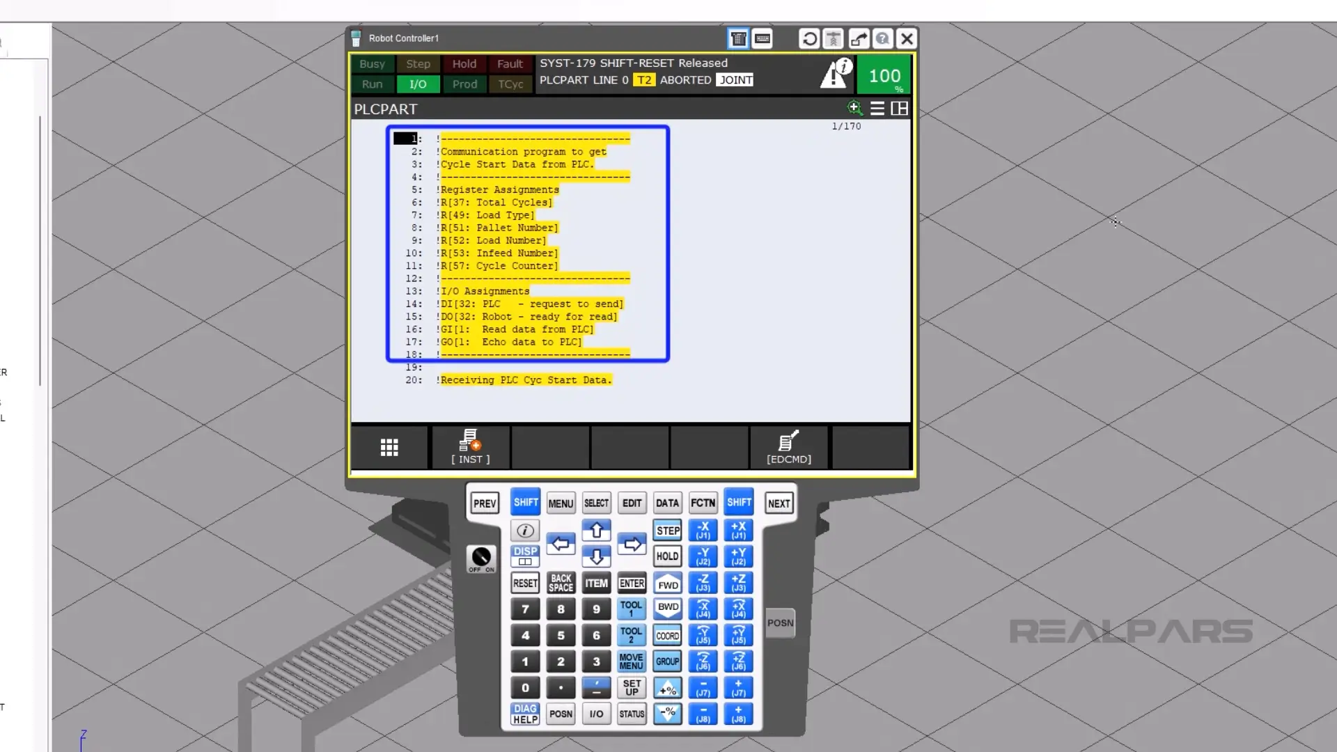
These are the first few lines of the program; this is a reminder of what is assigned to what. Keep in mind that this is the default, and you may need to amend this data if it doesn’t match your use case.
Now I will explain the program in simple terms. Lines 20 through 35 will set the total number of cycles.
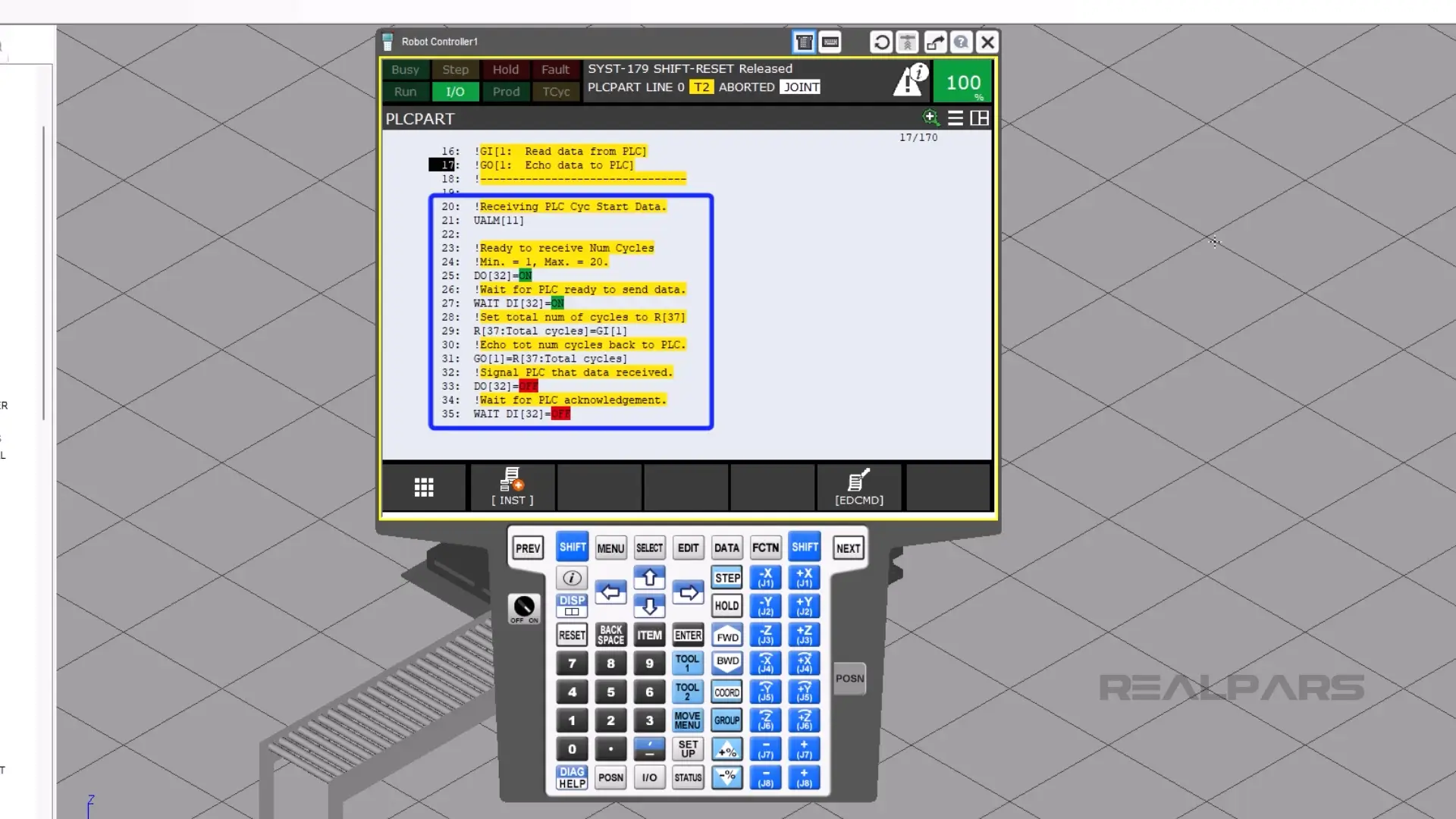
On line 21, the top of the teach pendant will display the words “Receiving PLC Cyc Start Data.”
Line 25 turns on DO[32] to tell the PLC that it’s ready to send some data.
On line 27, the PLC then turns on DI[32], signifying that it is ready to receive data.
On line 29, the robot takes the number in the PLC that is used for the total number of cycles and assigns that value to numeric register 37.
Then, on line 33, the robot tells the PLC that it sent the data.
Then on line 35, the PLC tells the robot that it got the data.
Looping through each cycle
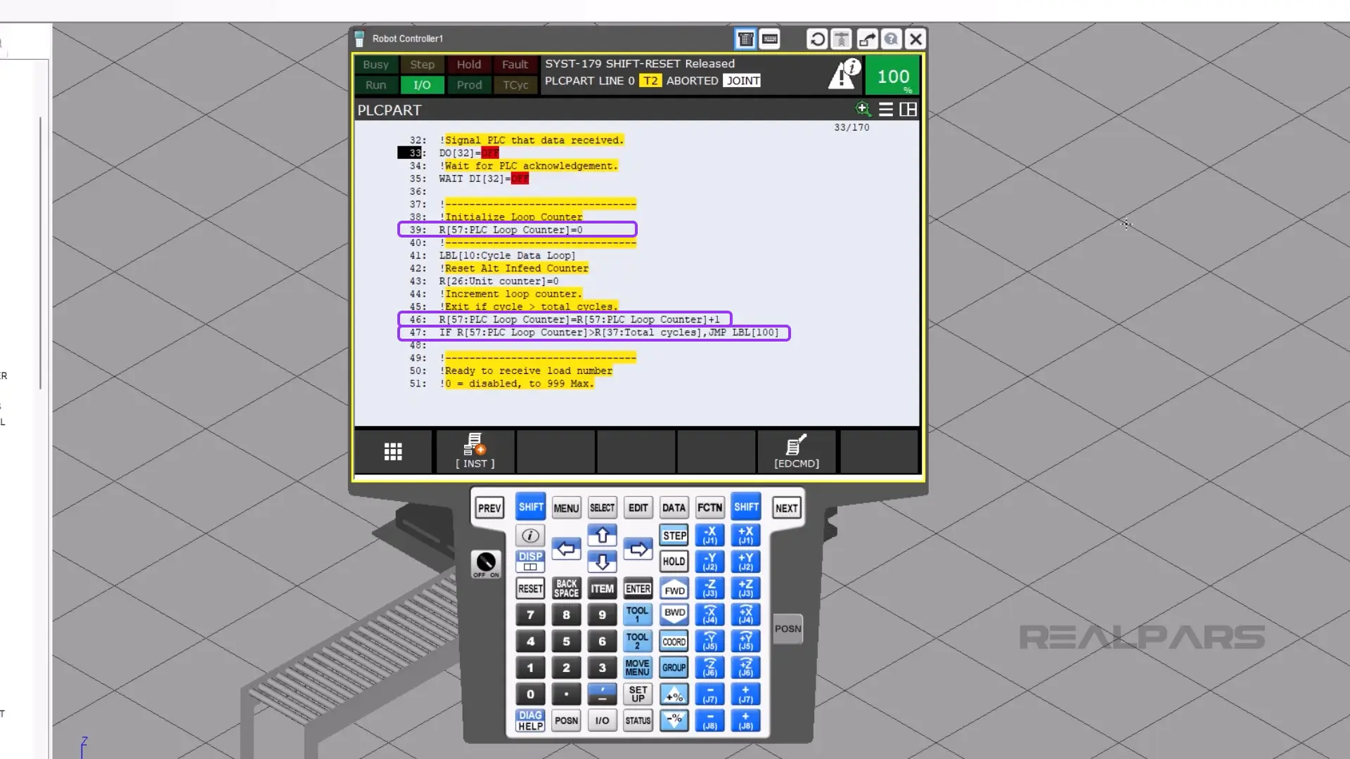
We then enter the loop. On line 39, the loop counter is reset.
Then the cycle count adds 1 to its current count, which is on line 46.
Line 47 compares the current loop to the total number of cycles. If the PLC loop count is greater than the total cycles numeric register, then the cursor will jump to the end of the program. The program will finish.
However, if the PLC counter numeric register is less than the total cycles numeric register, then the program continues to run.
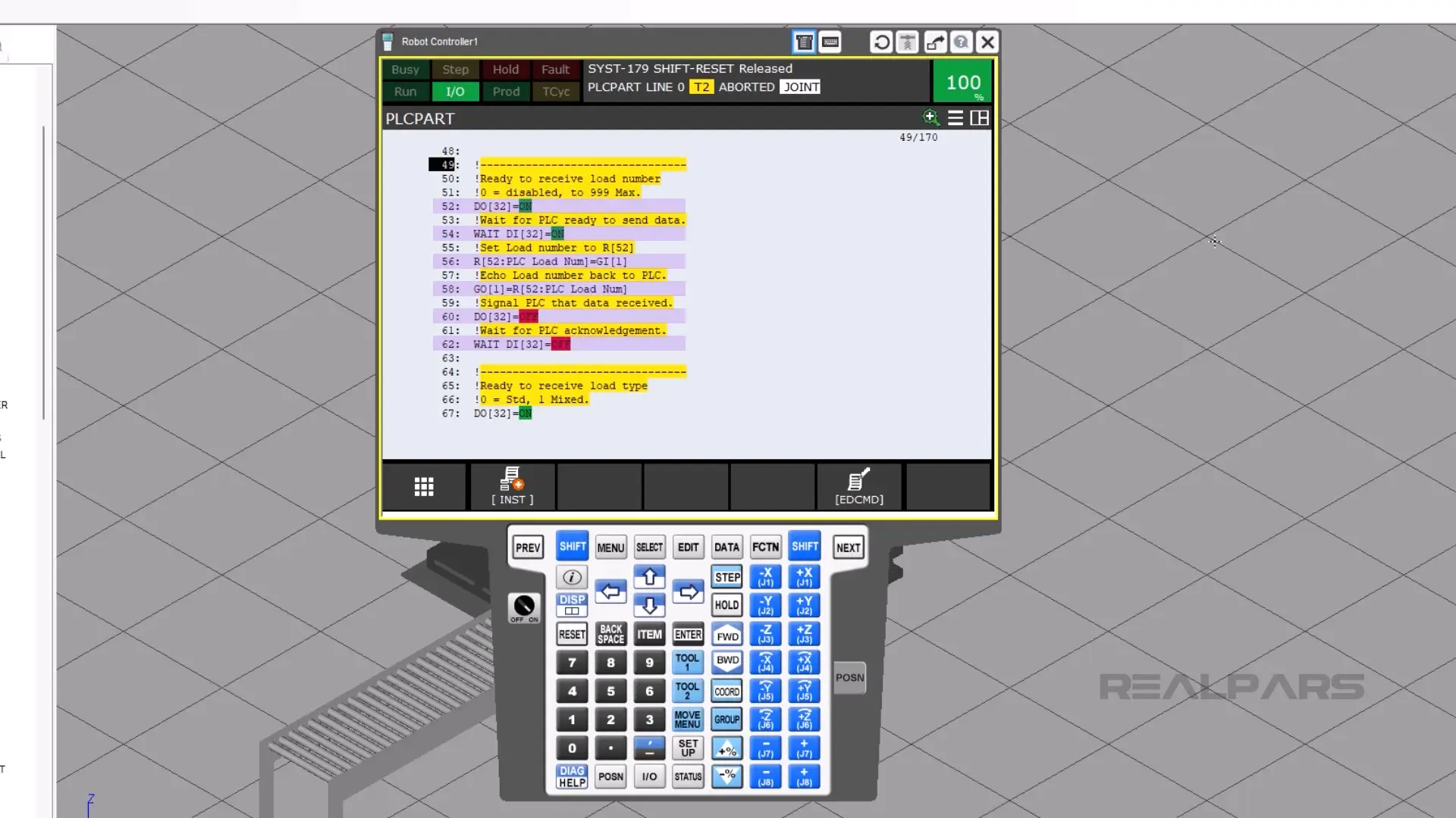
On line 52, the robot turns on its DO[32], which tells the PLC that it is ready to send data.
Right before the PLC turns on DI[32], the PLC needs to put the unit load number into GI[1].
Then the robot waits for the PLC’s response on line 54 using DI[32].
The robot then moves the data into R[52], which is what the robot will use.
To make sure that the robot got the data correctly, the robot will echo out the same R[52] to GO[1].
DO[32] turns off, and the robot waits for DI[32] to turn off.
The rest of the program will then repeat itself.
This handshake will continue for each of the following pieces of data:
- Unit load type
- Pallet number
- Layer number
- Unit number
- Infeed number
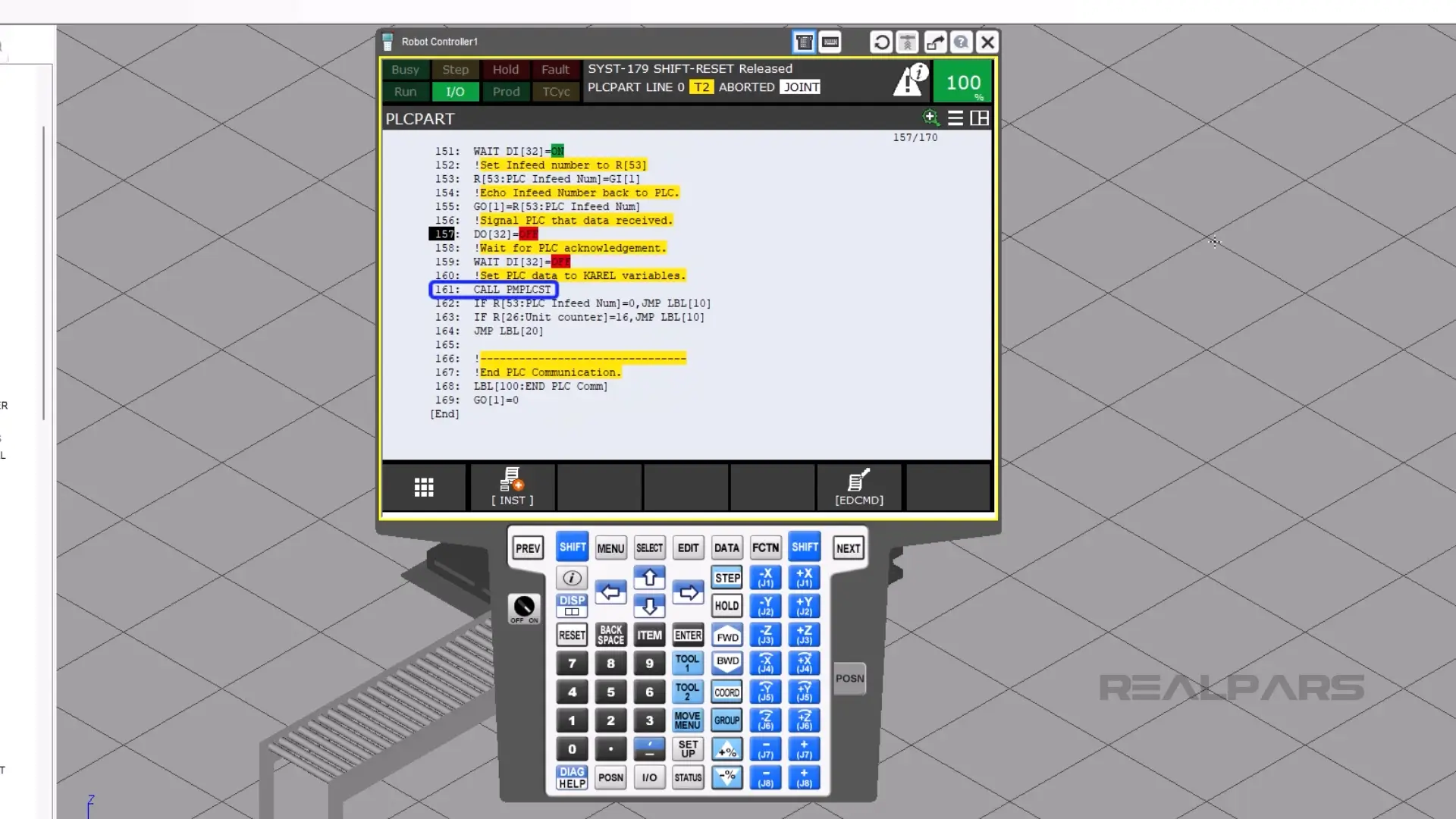
Lines 141 and 161 call the program PMPLCST, which assigns the data registers to a Karel program that talks to PalletTool.
Summary
In this article, you learned what PLCPART.tp does, how it communicates palletizing data between the robot and the PLC, and how it processes each cycle to assign the correct unit load, pallet, and infeed values.