
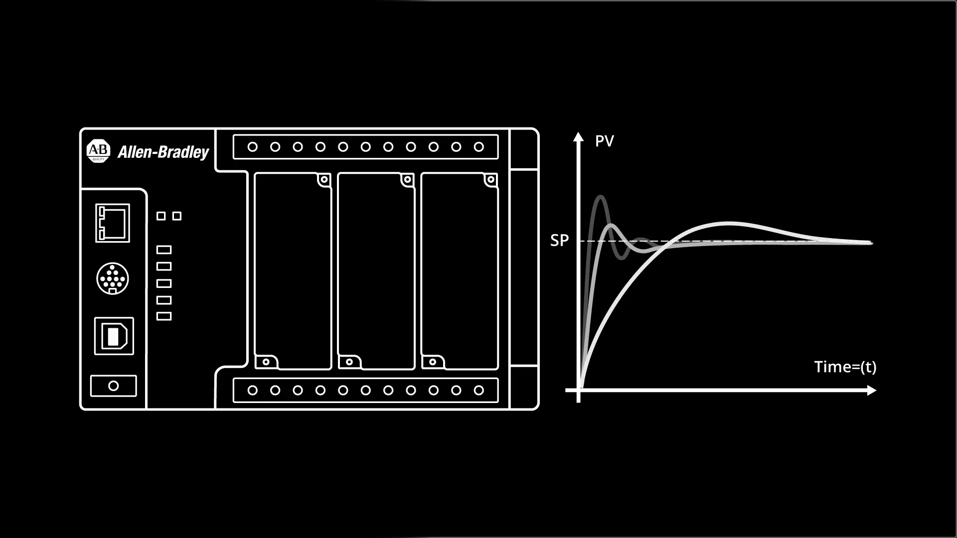
PID loops are used in process industries to keep setpoints such as temperature, pressure, and level within limits.
Watch the video to learn more, or scroll down to read the rest of the article.
If you are new to the concept of a PID loop, you can learn more about them in our blog post PID Controller Explained.
In this article, I’m going to show you how to implement a PID loop in a Micro800 PLC using Connected Components Workbench and demonstrate how the PID loop controls the level in a tank.
Program the PID loop
Let’s switch over to Connected Components Workbench to set up our PID loop.
In Connected Components Workbench, I create a new project by clicking on File > New.
In the New Project dialog, I give the project a name and specify where on my computer it will be stored. Finally, I click Create to create the project.
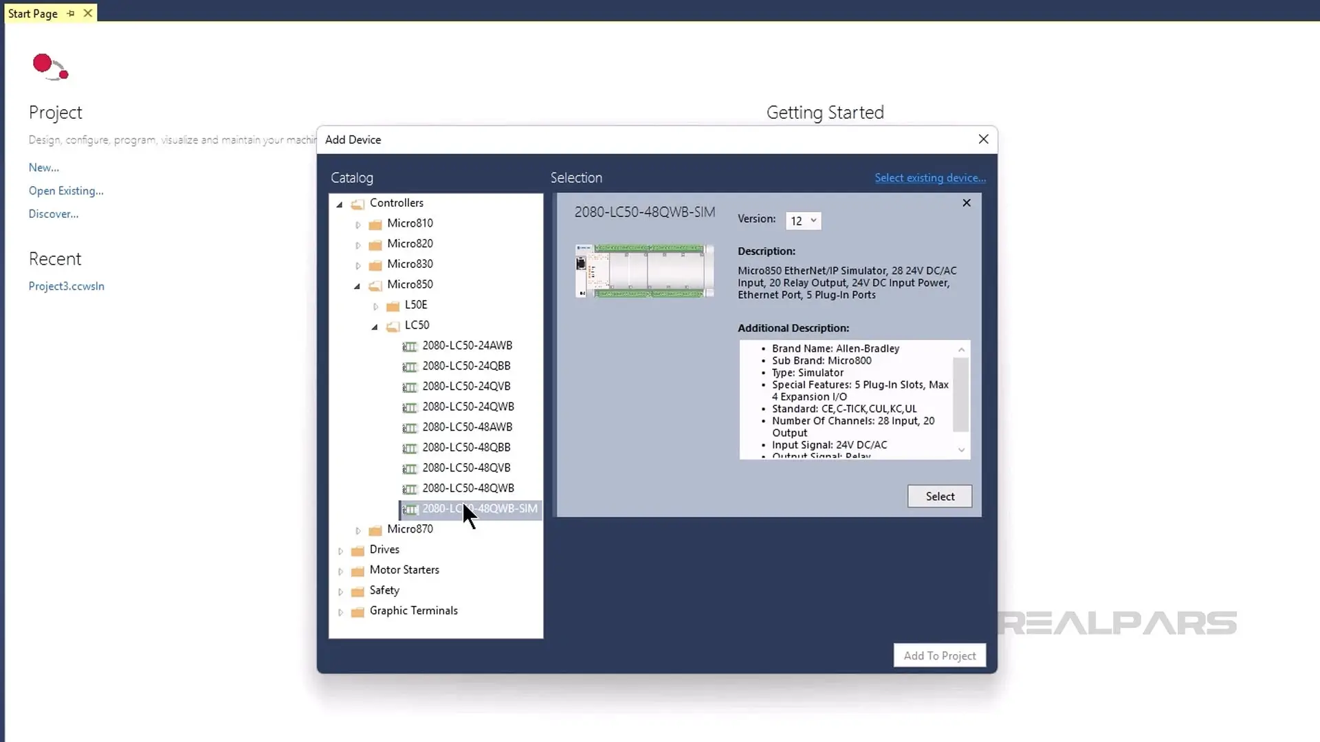
In the Add Device dialog, I select a 2080-LC50-48QWB-SIM PLC and click Select to add it to my selections. Then I click Add To Project to add my selections to the project.
In the Project Organizer, I double-click on Global Variables to open the Global Variables table and then declare the variables that I will use in this demo.
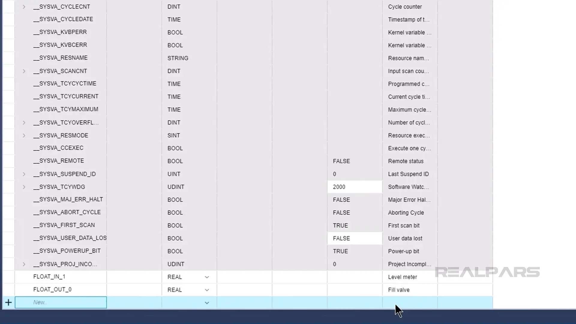
Once the variables are declared, I close the Global Variables table.
Then I right-click on Programs and select Add > New FBD: Function Block Diagram to add a program to the project.
I double-click on the new program to open it and drag an Instruction Block from the Toolbox on the right and drop it on the canvas.
I double-click on the Instruction Block to open the Instruction Block Selection dialog and search for PID. From the search results, I select the PID Instruction Block and click OK to add it to the project.
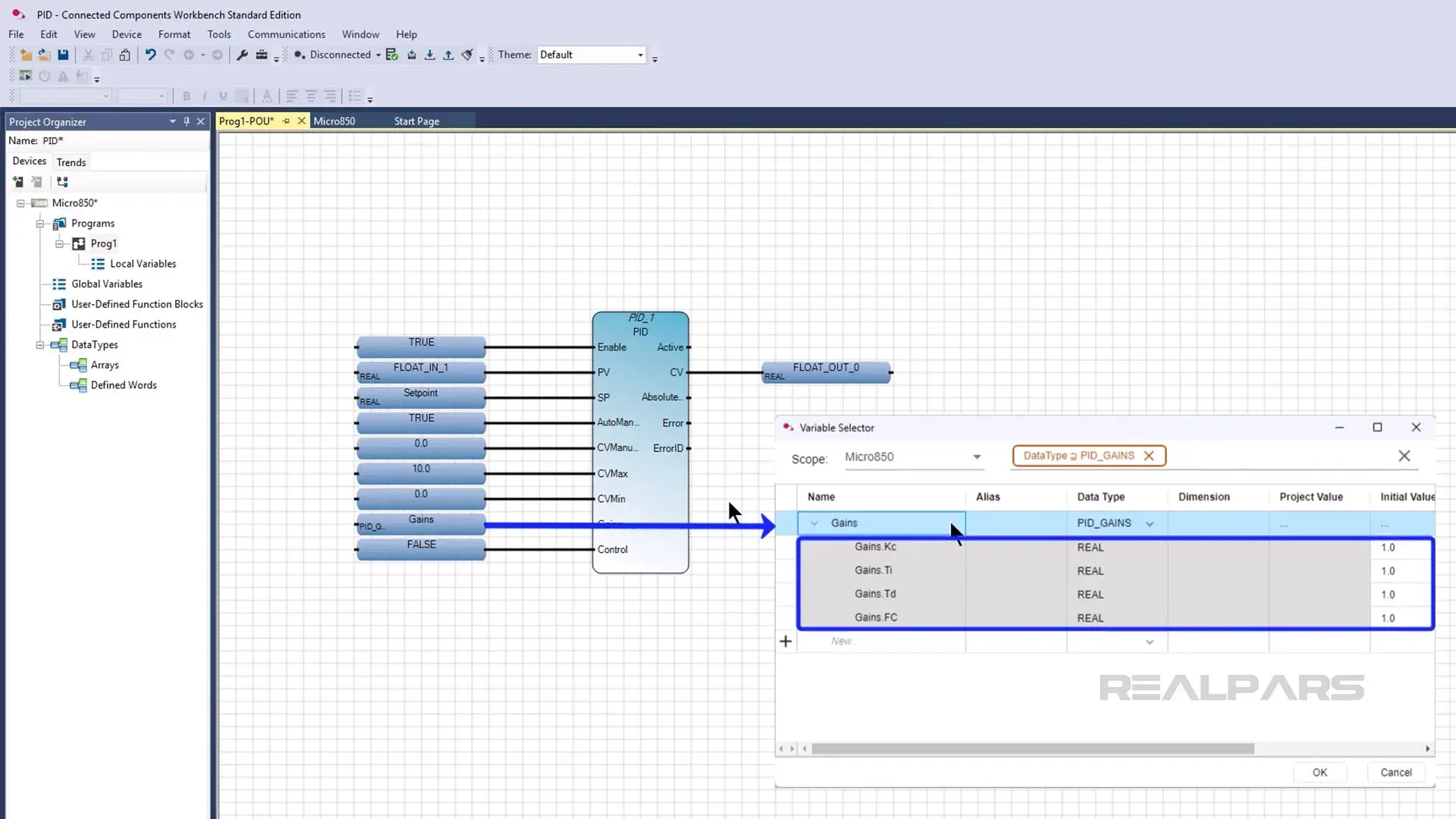
I parameterize the interface of the instruction as shown here and set each of the gains in the Gains variable to 1.
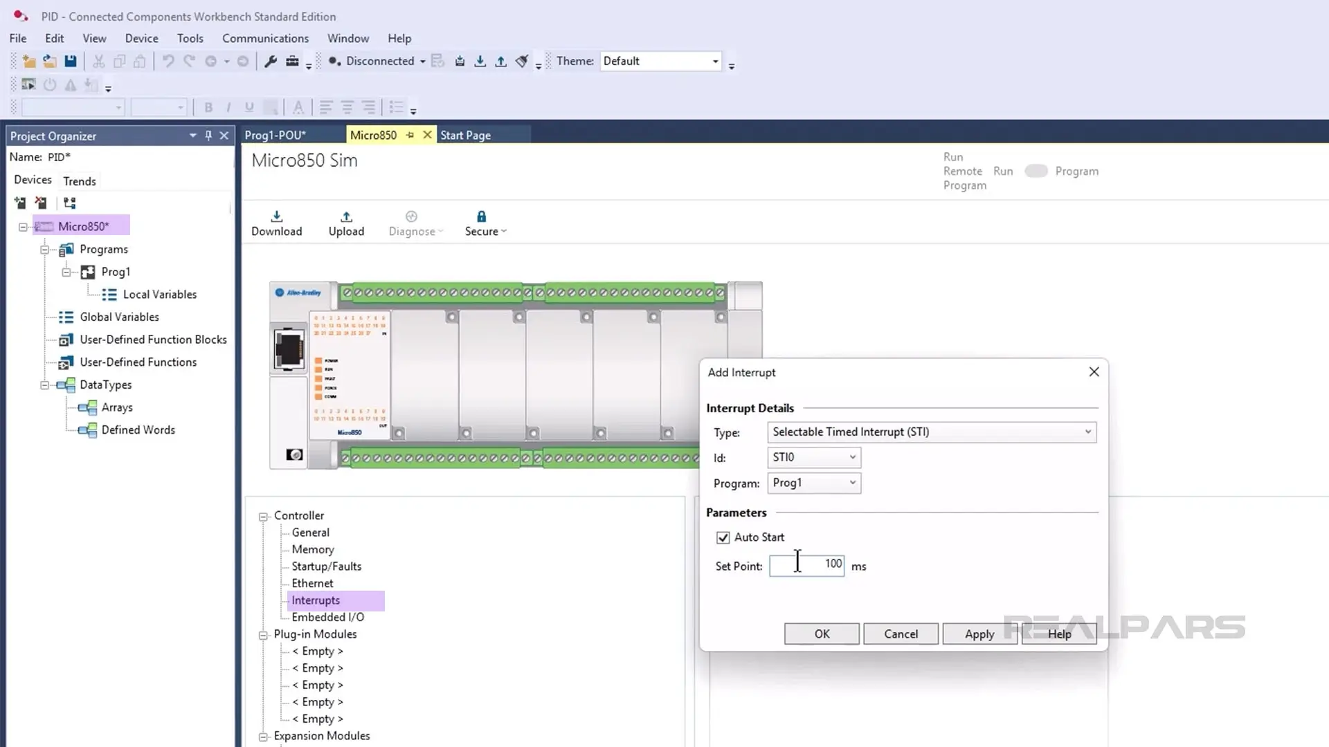
After configuring the instruction, I double-click on the controller in the Project Organizer and open the Interrupts tab. In this tab, I click Add to add an interrupt.
I set the interrupt type to STI and the program to Prog1. Then I click the Auto Start checkbox and configure the interrupt to run every 100 milliseconds.
Finally, I click OK to store the configuration.
Now that our project is configured, we can set up a trend to see how the PID loop performs.
Configure a trend
In Connected Components Workbench, you can use trends to monitor the values of variables over time. If you are using Connected Components Workbench version 22, you will need to install the Trends tool before you can use trends in Connected Components Workbench.
To configure a trend, I activate the Trends tab in the Project Organizer and click Add Trend.
Then I click the plus button to add a Trace, which is a variable to monitor.
In the dialog that opens, I select FLOAT_OUT_0, FLOAT_IN_0, and Setpoint as the variables to Trace and click Add to add them to the Trend.
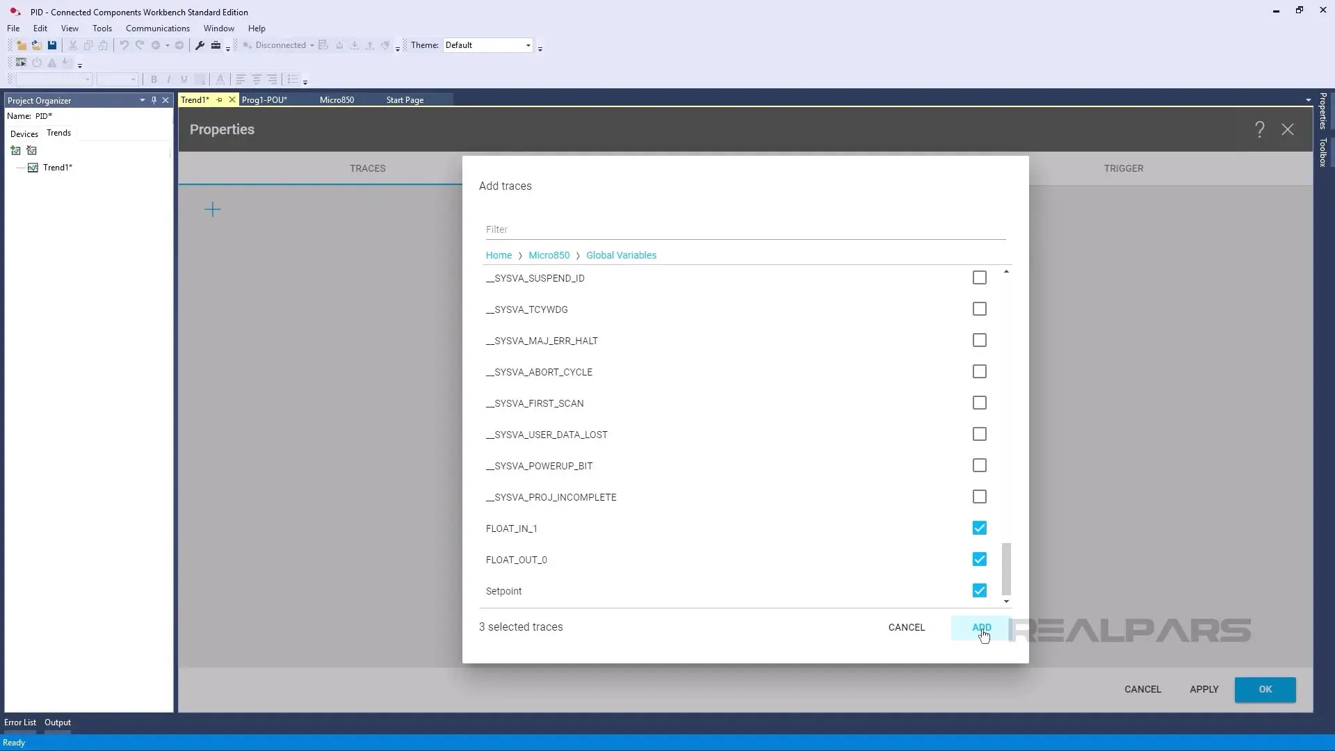
I click OK to store the configuration.
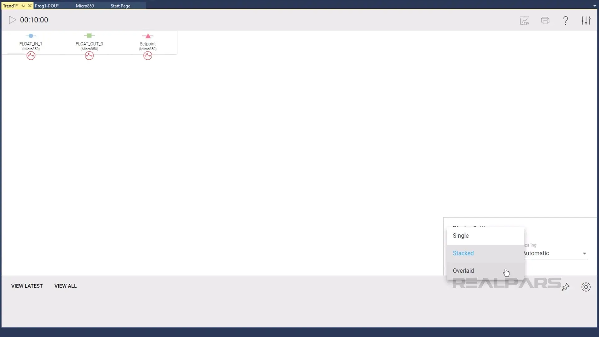
On the Trend page, I click the settings icon in the bottom right corner and change the Y-Axis configuration from Stacked to Overlaid.
Now, we are ready to test the project and see how this PID loop would control a real process.
Test the PID loop
To test this PID loop, I download the project to the Micro800 Simulator and put the Simulator in Run mode.
Next, I open the Level Control Scene in Factory IO.
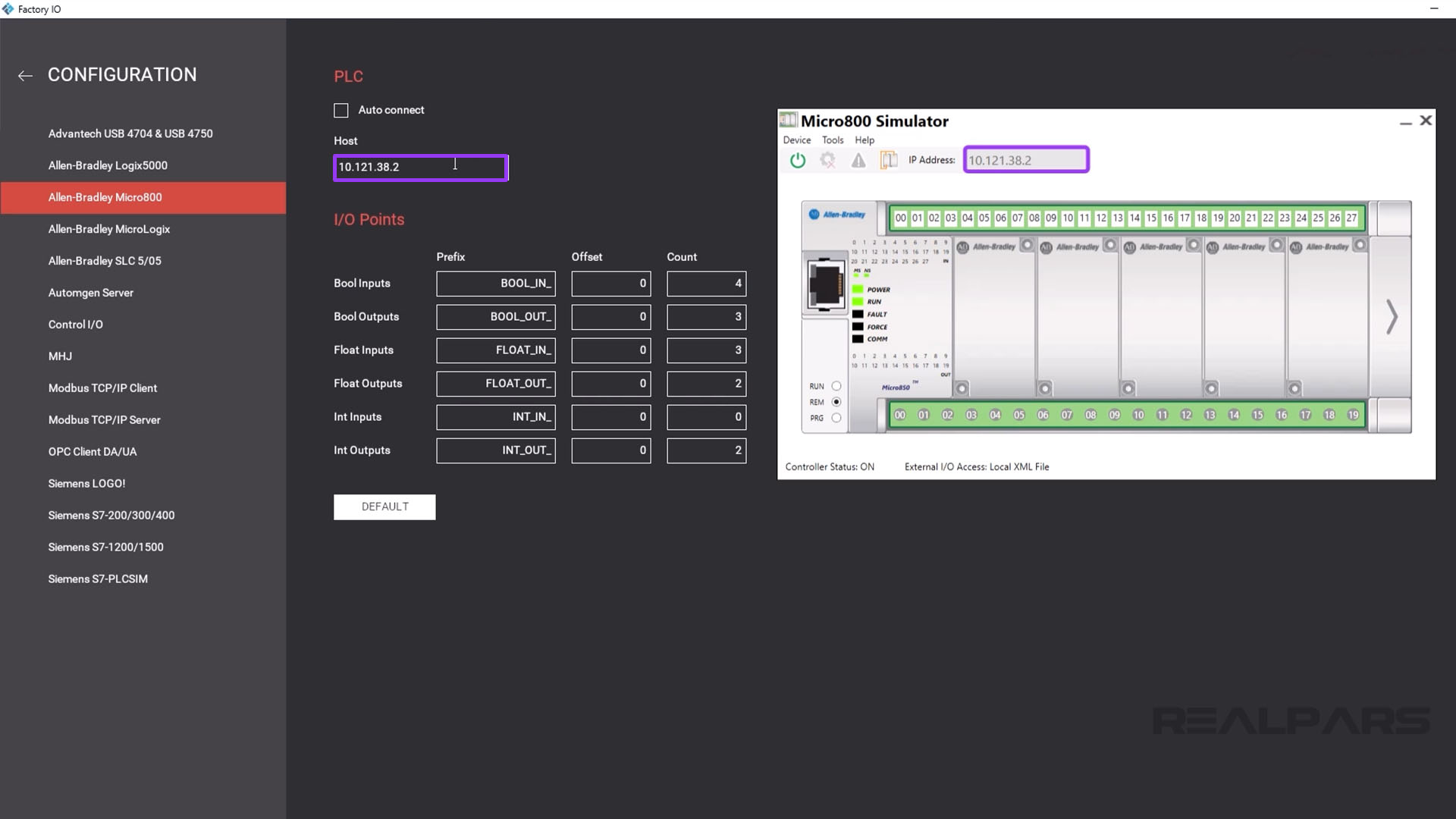
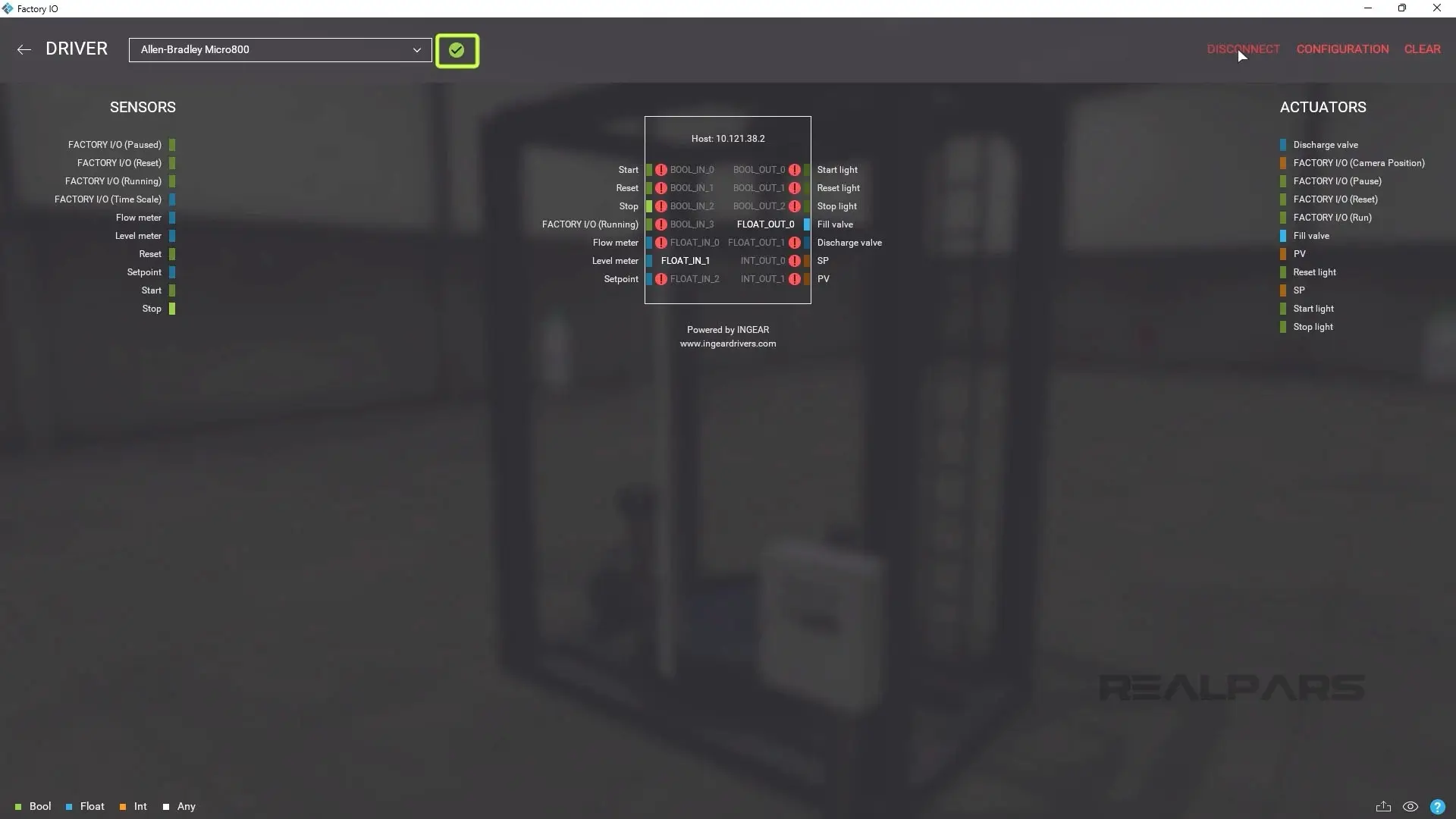
When the scene is open, I open the Driver configuration by clicking on File and then Drivers. In the dropdown menu, I select the Allen-Bradley Micro800 driver and click Configuration to open the Driver Configuration window.
In this window, I set the Host IP Address to match the IP address of the Micro800 Simulator.
With the configuration done, I click the back arrow to return to the Driver Configuration and click Connect. The green tick indicates that the scene is now connected to the Micro800 Simulator.
I close the Driver Configuration window and run the scene by pressing the Play icon.
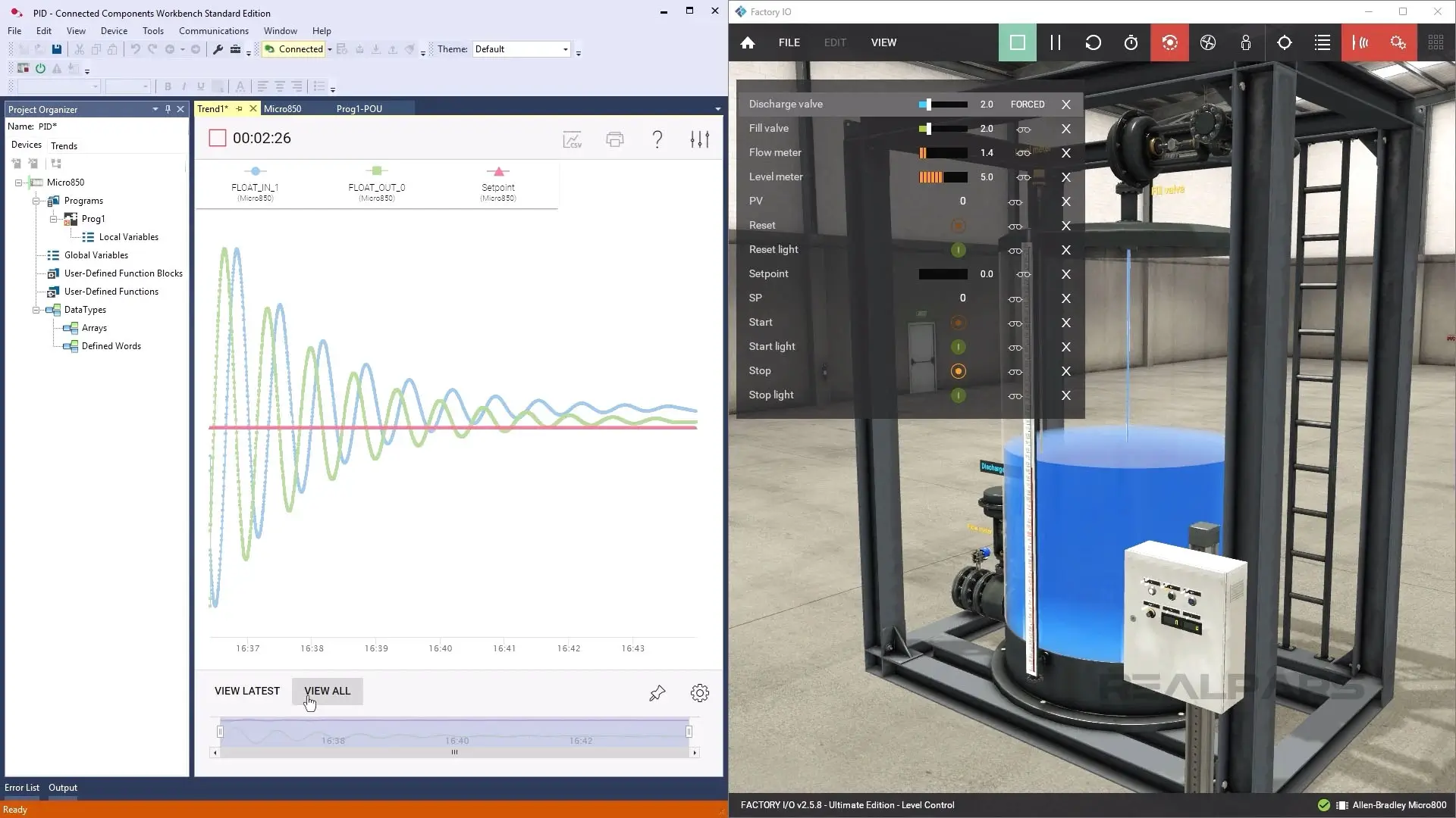
The Tank starts filling, and I open the Discharge valve slightly to allow some water to flow out of the tank.
In Connected Components Workbench, I open the Trend and click the Play icon to start running it. You can see in this trend that the PID loop is adjusting the Fill Valve to try to maintain the target setpoint.
Wrap-Up
In this article, we learned how to configure a PID loop in a Micro800 PLC, how to use a Trend to monitor a PID loop, and saw how a PID loop would control a real process using Factory IO.
In this demo, we used arbitrary gains. In a real process, we would spend time tuning the PID to make sure it performed well. Unfortunately, since tuning is a complex topic, it is outside the scope of this article. We’ll cover using auto-tune to tune PID loops in the PID with Micro800 PLCs course.