

We get many questions about the basics of electrical control panels, such as what devices and equipment we typically use, how the devices are wired, how to keep the control panel and the cabinet within a normal temperature range and so on.
To answer some of these questions, we decided to go to one of our partner’s workshop and shoot a practical video reviewing an actual electrical control panel, for you to see what the basic components of a control panel are, how they are wired, the function of a thermostat and so on.
The control panel that we are going to review is used for a system that turns wastewater into clean water.
An example of wastewater could be the water that comes out of the bathroom or the toilet. This control panel controls the system that cleans this wastewater and turns it into the drinking water. Pretty cool, huh?
Control Panel Size
The control panel that we are reviwing here is a 2-door control panel.
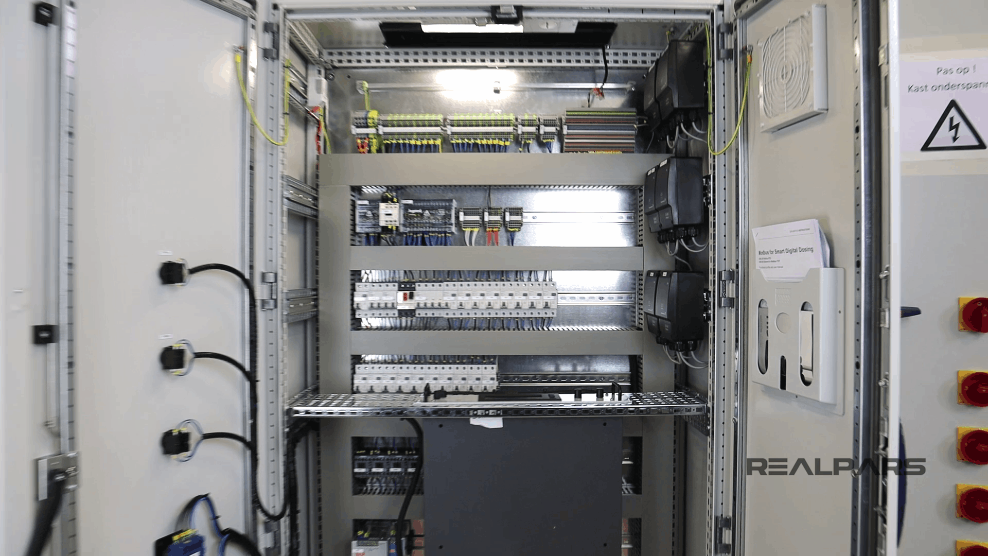
As you may remember from the previous RealPars article about the basics of a control panel, we mentioned that we name control panels based on the number of doors that they have.
So you have one-door, two-door or three-door control panel enclosures depending on how big of a panel you have. The more equipment and devices you have, the larger the control cabinet you will need.
Switches on the Panel Door
On the front of the panel, we have some switches that are connected to the PLC inputs and outputs.
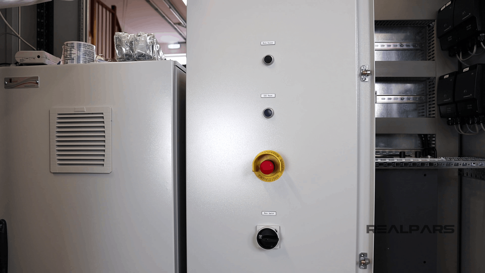
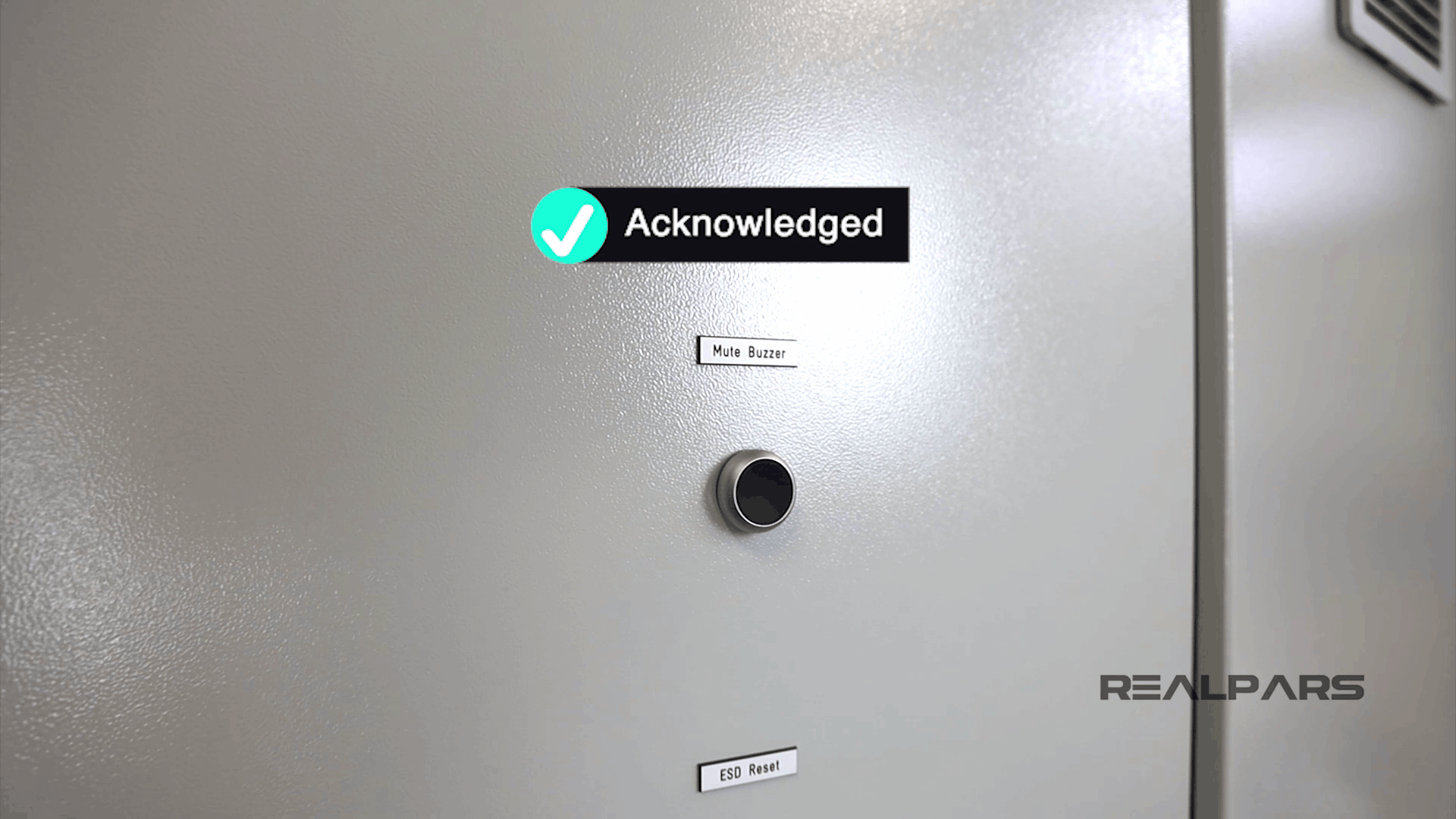
Mute Buzzer
The first switch that we have on the panel door is Mute Buzzer.
This is the button that you use and press when there is an active alarm on the system.
When there is an active alarm on the system, the technician, engineer, or whoever is responsible on the factory floor, presses this button to acknowledge the alarm and mute the buzzer.
That’s why we often call this the acknowledge button as well.
But you may ask, why do we do this? Why should we press this button and mute the buzzer, acknowledging the alarm?
Well, first off, to state the obvious, by pressing this button when there is an active alarm, you can only mute the buzzer.
Muting the buzzer means the alarm is still there and still visible on the HMI, but the buzzer has stopped sounding.
But why should we mute the buzzer and make it silent?
Well, the answer is simple, because you don’t want that annoying, loud sound of the buzzer in your ears while you are working to resolve the issue.
So when there is an active alarm on the system, and it’s making that crazy loud noise, the engineer or technician can press this button to mute the buzzer, and in doing so, acknowledge that they are aware of the alarm as well.
Therefore, next time that you see an alarm on the HMI, but there is no sound, it probably means that somebody has already acknowledged the alarm.
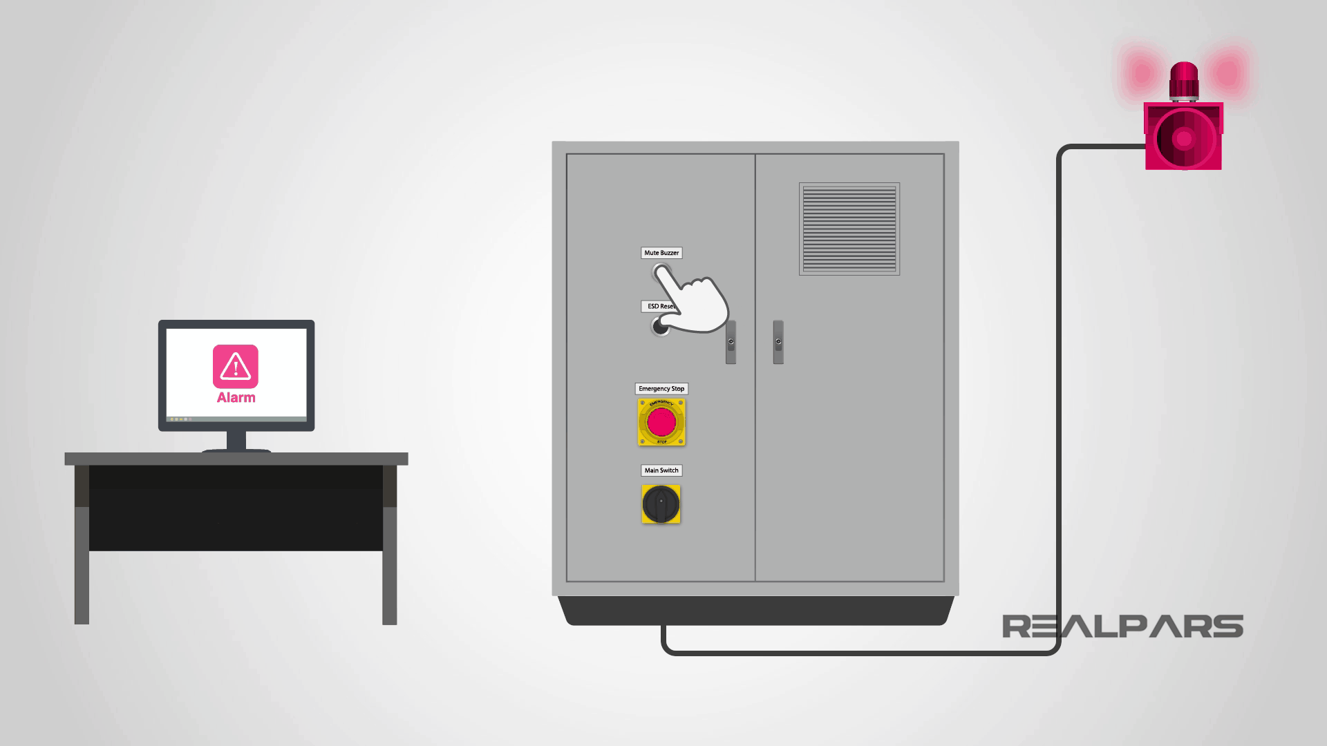
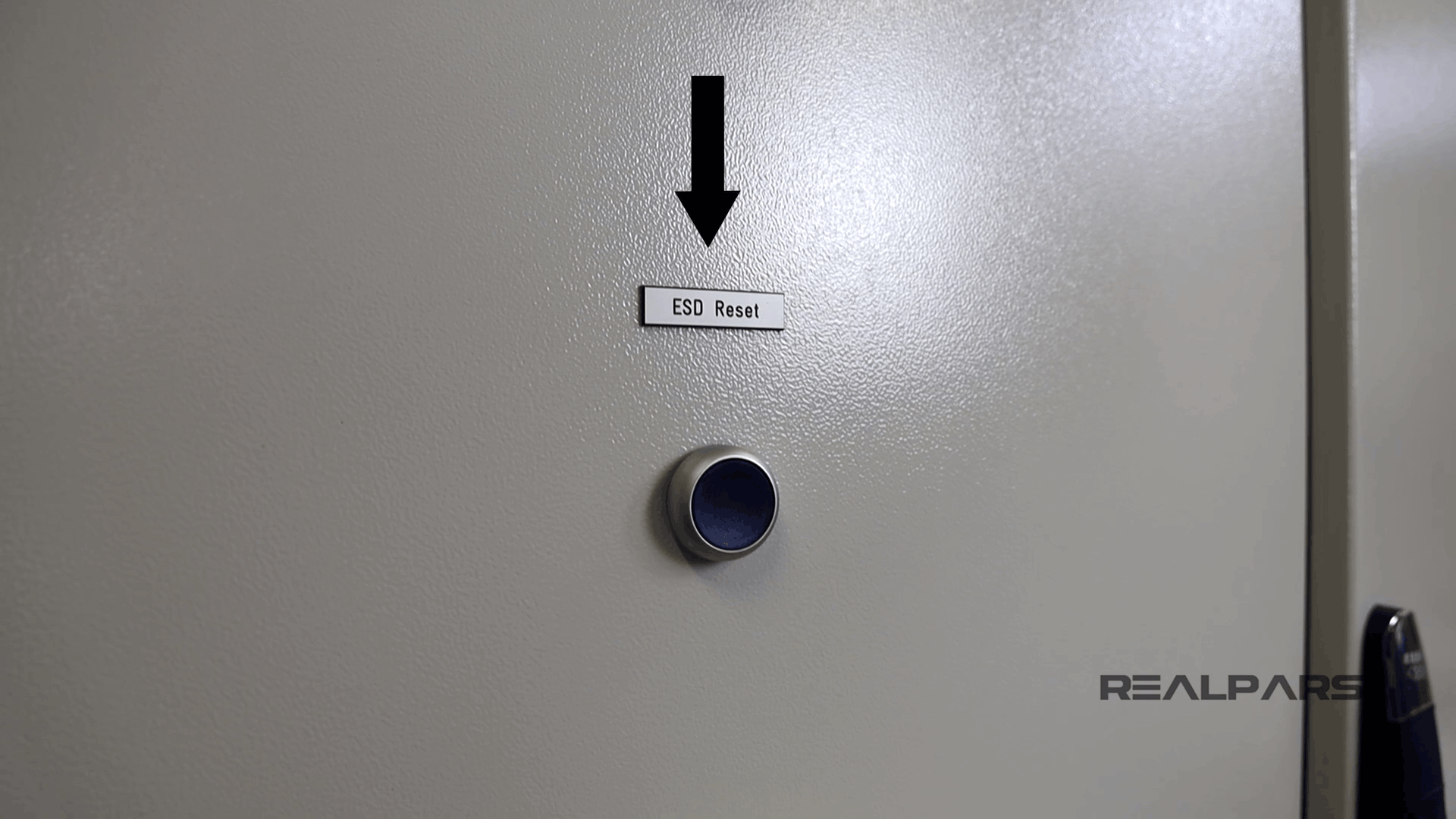
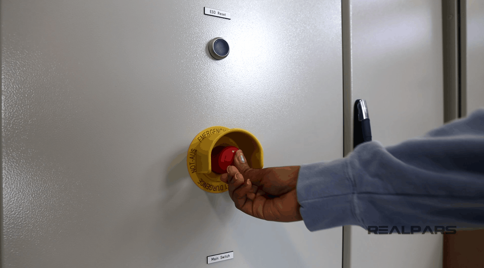
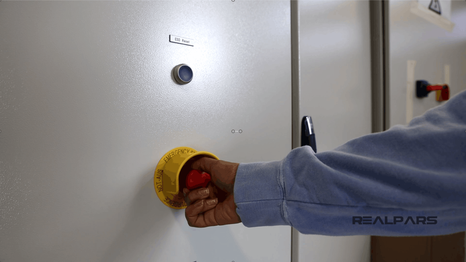
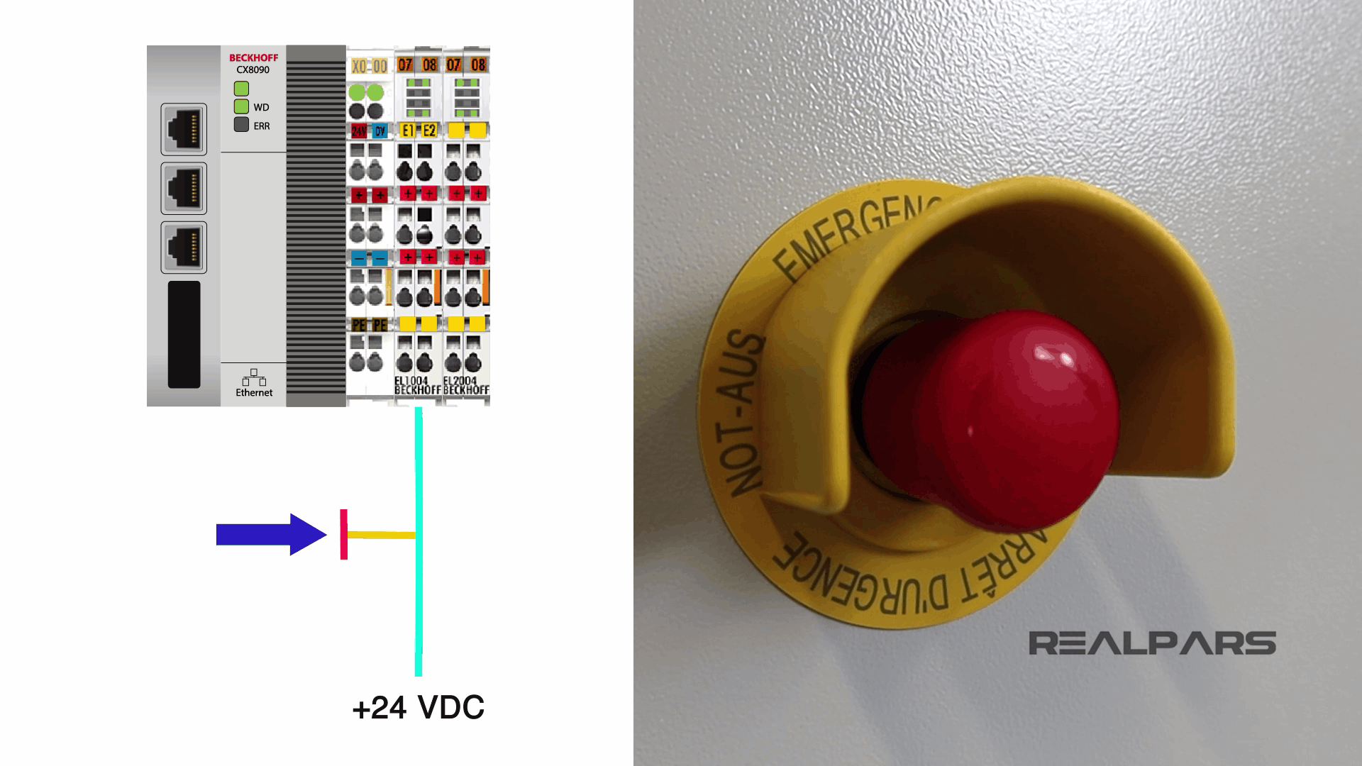
ESD Reset and Emergency push button
Next, we have the ESD Reset which we will get into shortly.
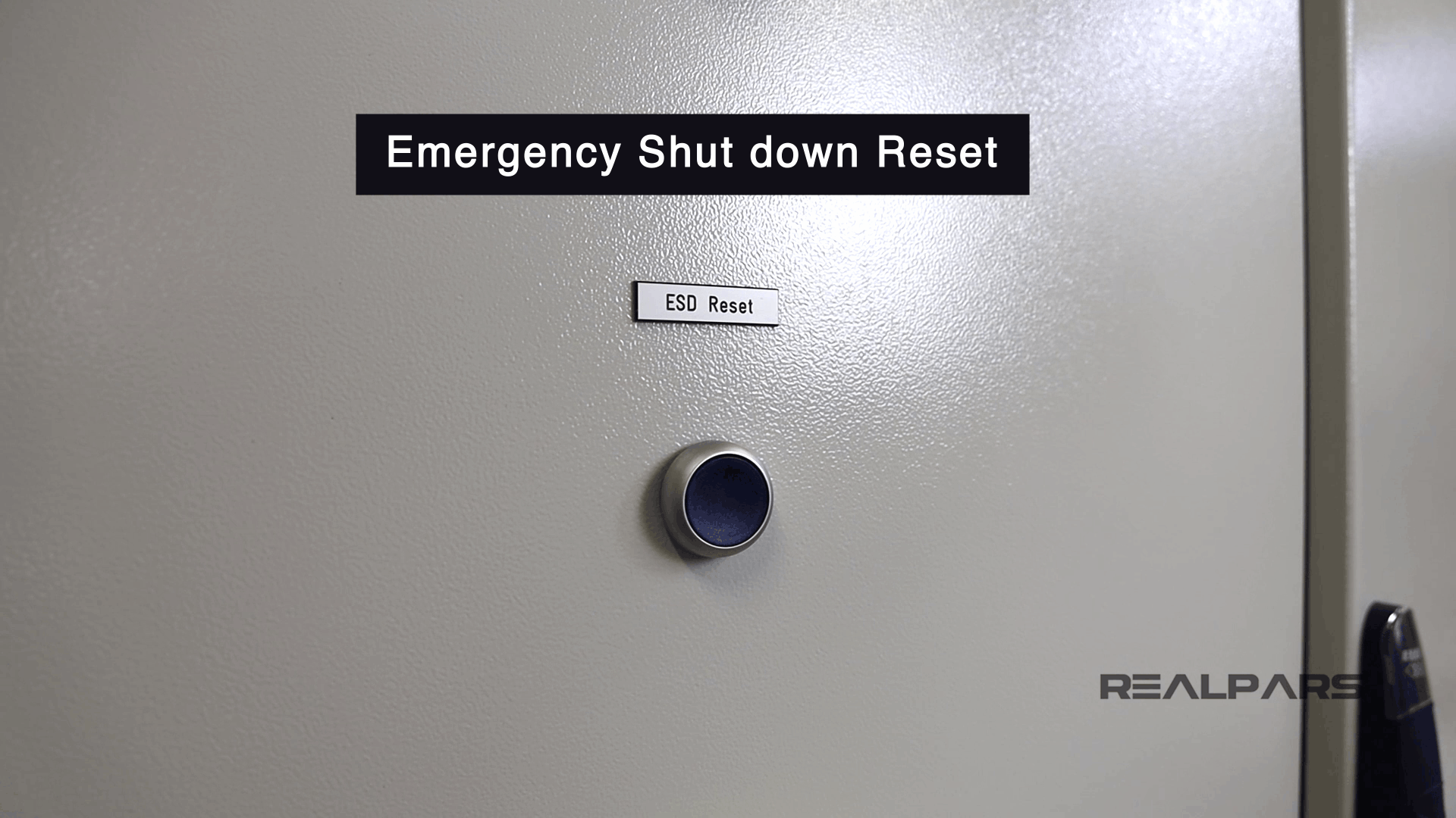
Below this switch, we have the big red Emergency Shutdown push button or the
E-Stop as it’s often called.
As the name indicates, you use this switch to shut down the whole system when there is an emergency, and by doing this you can prevent damage being caused to the system, or the people around it.
As you can see, it has some guarding around it, called a shroud. This will prevent the button from being used unintentionally.
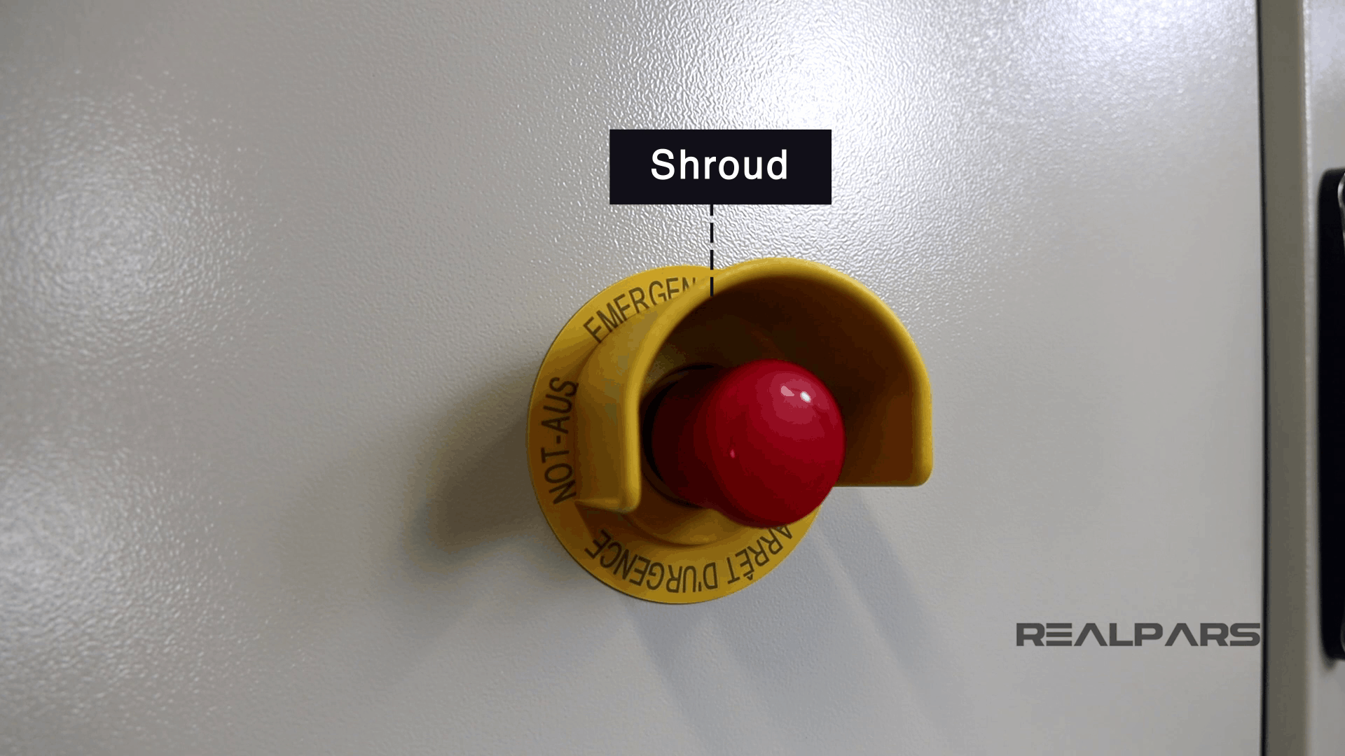
Emergency-Stop devices are always close to where people work in order to be useful, but we have this shroud around it to prevent any unwanted use. Why? Because if someone presses this button unintentionally the whole system will be shut down completely.
Now, when you press the Emergency-Stop switch, a red alarm indicator appears on the HMI screen.
After the emergency is gone and you want to run the system again, you can press the ESD Reset button, or Emergency Shut down Reset, to clear the alarm and the indicator on the HMI.
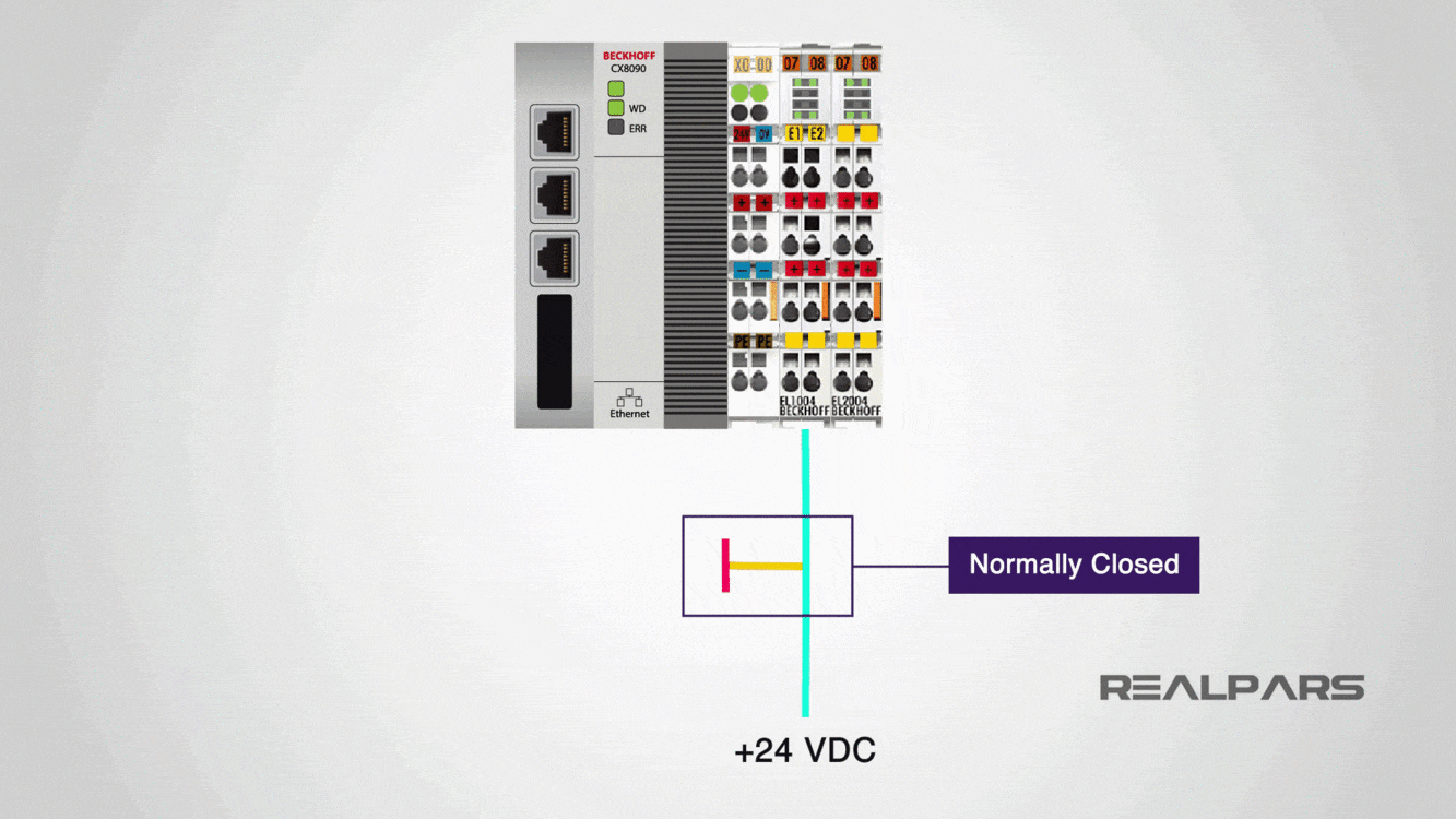
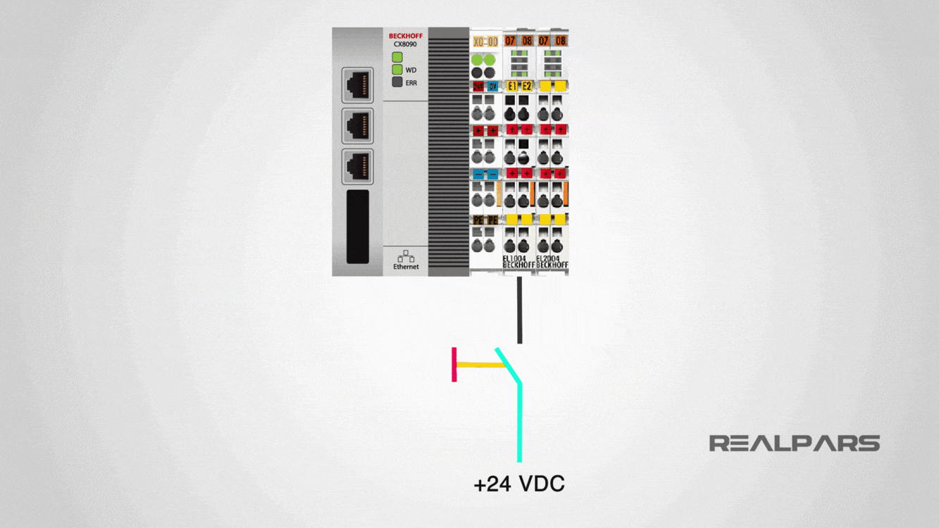
An Emergency-Stop switch is designed to work as a normally closed switch. That means this switch is closed in normal operation, and when it is pressed, the switch opens.
Why the Emergency switch should be normally closed?
Now you may wonder why we have this Emergency-Stop as a normally closed switch. Well, let’s say that you have this as a normally open switch instead.
That means the switch is open in the normal state and will be closed when it’s pressed, right?
Now, let’s say that unaware to you, a wire that is connected to the lower part of the contact has been disconnected and you are not aware of it.
Now, what happens when there is an emergency? Well, when there is an emergency, you press this Emergency-Stop switch, BUT the switch will not work.
WHY? Because the wire has been disconnected and you are not aware of it.
You never want to put yourself in a situation like this. Because this is too late and also too dangerous.
So what’s the solution here?
Well let’s repeat the same scenario but this time replace this normally open Emergency-Stop switch with a normally closed switch.
With this normally closed switch in the normal state, there is a 24-volt signal connected to the PLC input, giving an Emergency-Stop healthy signal to the PLC, or other safety systems.
When the switch is pressed, the healthy signal will be lost, and that’s how the PLC, or safety system, knows to shut down the whole system. Right?
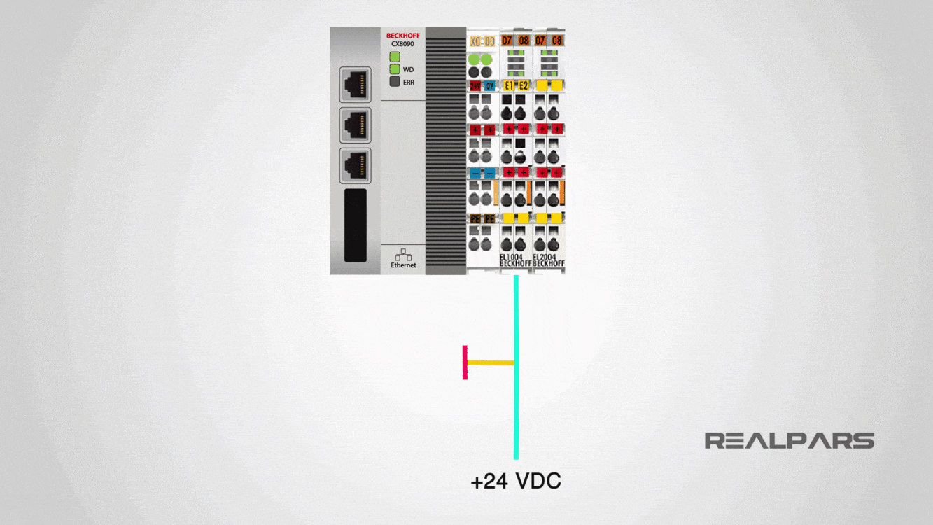
Now imagine the switch is back to the normal mode, but this wire gets disconnected for some reason. What happens now?
In this situation, the healthy signal will be lost, and the PLC sees that as someone pressing the switch, right? So it shuts down the whole system.
So with this Emergency-Stop switch, if the wire connected to the switch breaks, the PLC shuts down the whole system.
Yes! an unwanted shut down is not what you want when a wire-break happens, but this is much better than having an emergency but not being able to shut down the system.
That’s why you always need to use a normally closed switch, for your Emergency-Stop.
Emergency switch lock mode
The Emergency-Stop that we have here goes to the lock mode when it’s pressed.
Now to unlock the switch and turn it back to the normal mode again, we can twist it, and the switch will get back to the normal mode again.
How the switches on the panel door are connected to the PLC
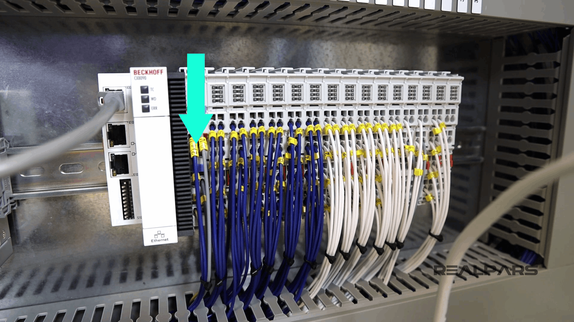
On the back of the door, you see that the switch is wired all the way to the PLC input.
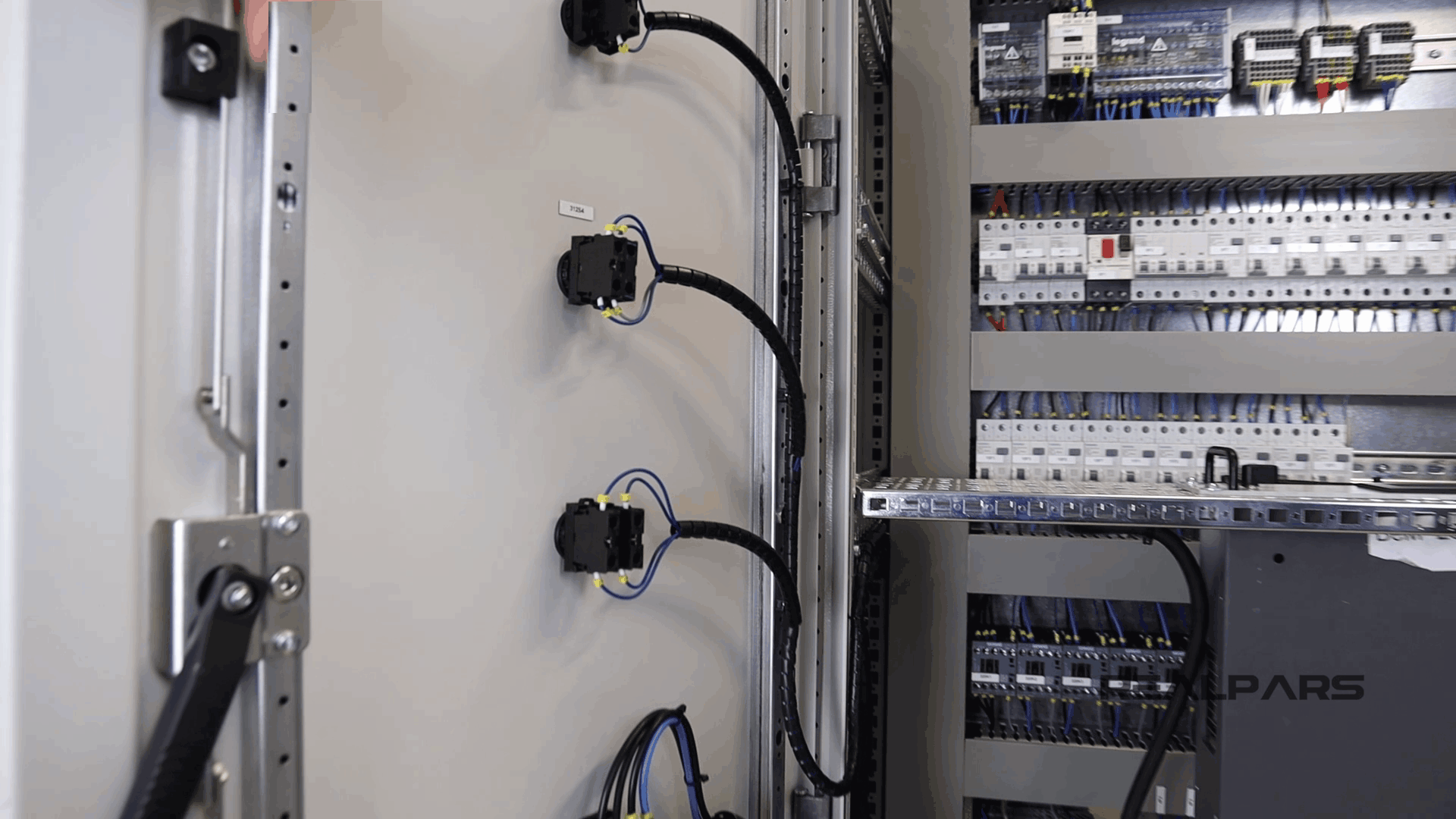
This is a BECKHOFF PLC.
The blue wires that you see in the image below are digital input and output signals; the white wires are analog inputs and outputs signals.
These wires come all the way from the sensors and actuators in the field and get connected to the PLC.
Of course, we only have these switches on the panel door connected to the PLC and the rest of the sensors and actuators will be connected to the PLC once we install this control panel in the field.
The Emergency-Stop that we have on the door is connected to the PLC digital input card as it only sends an on and off signal to the PLC input.
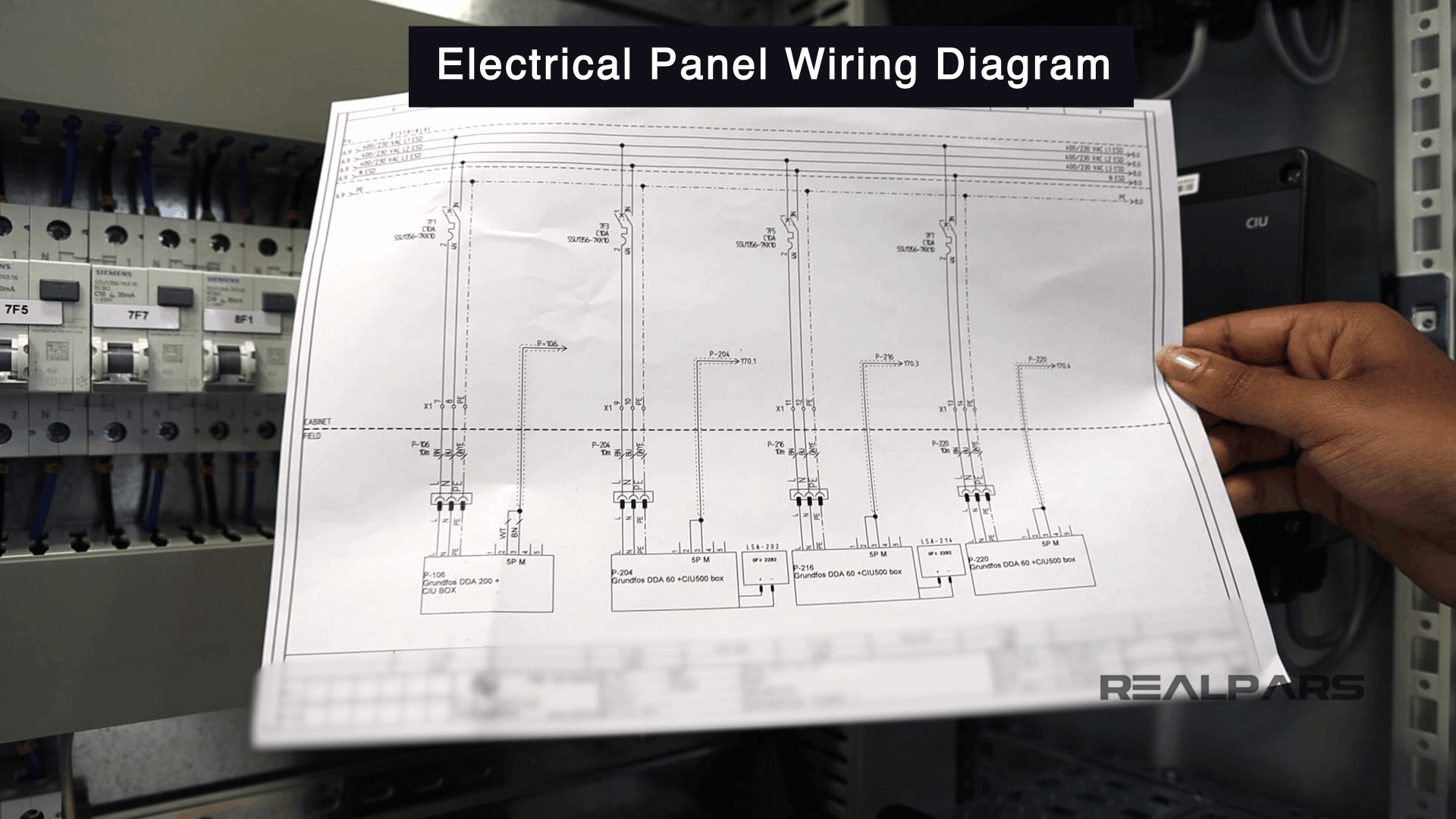
Wiring diagram
Now you maybe be curious how you should know which input on the PLC you should connect the Emergency-Stop to.
Well, this is simply done based on the wiring diagram. In a later article, we will get into the details of the wiring diagram and show you how simple it is to read and carry out the control panel wiring.
Overview of the main Control panel components
Now let me give you an overview of all of the important components that we have for this panel and also see how they are connected.
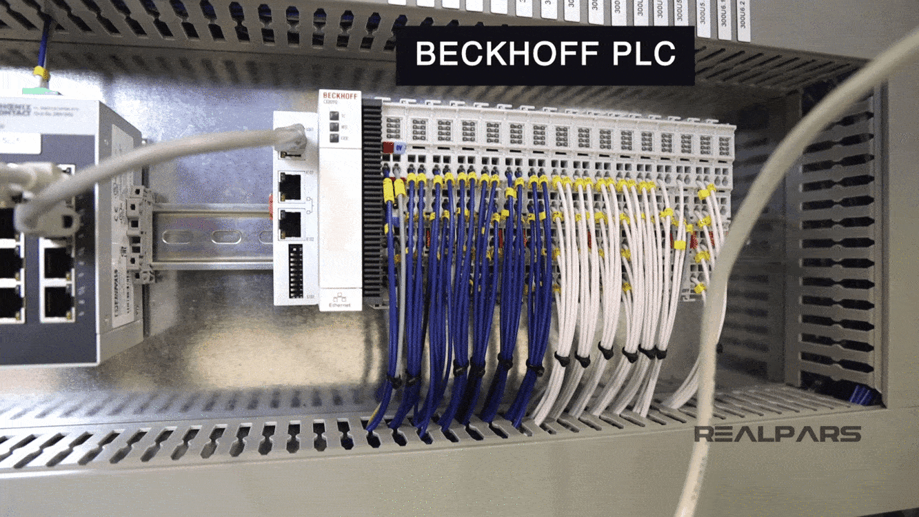
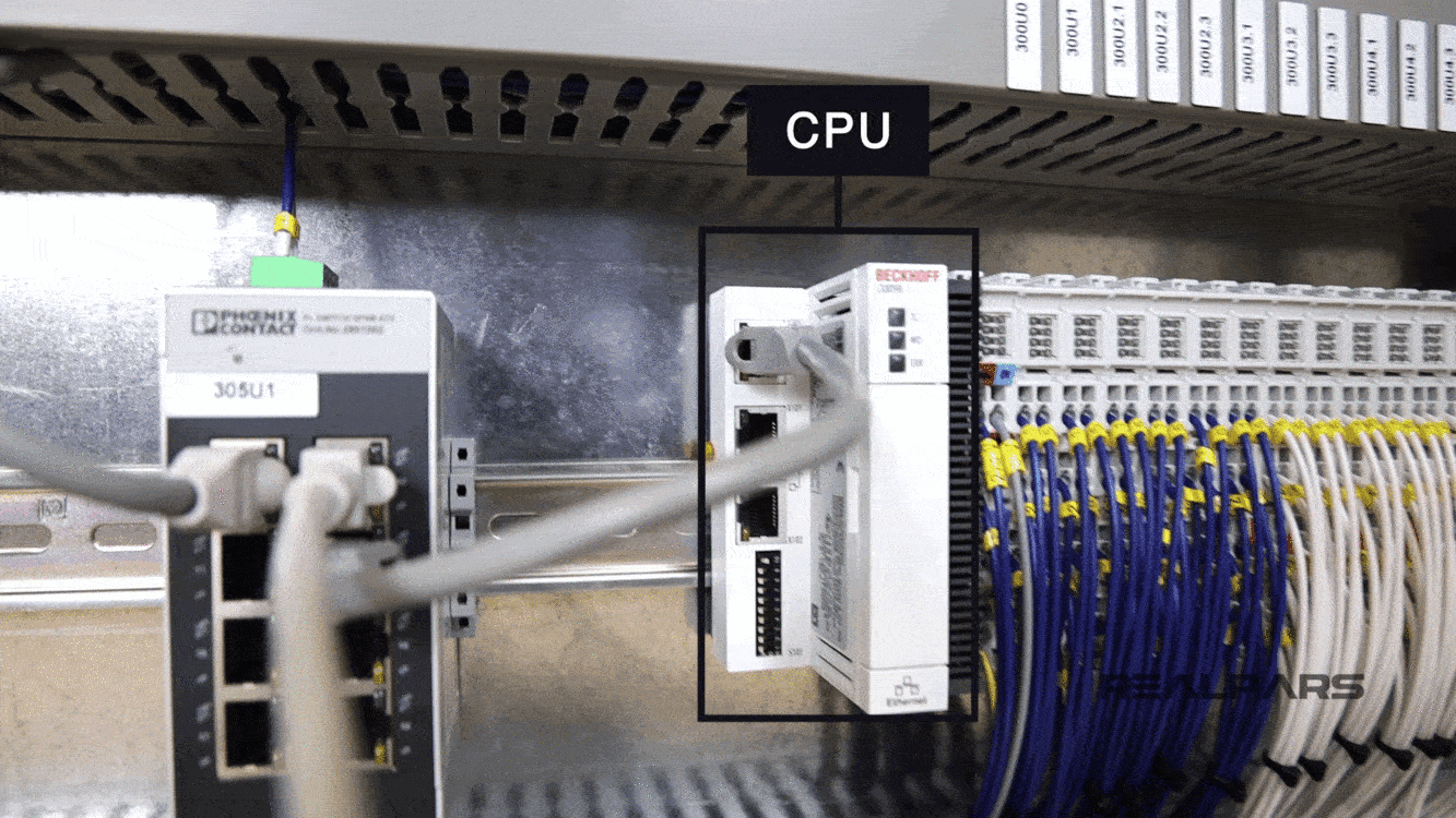
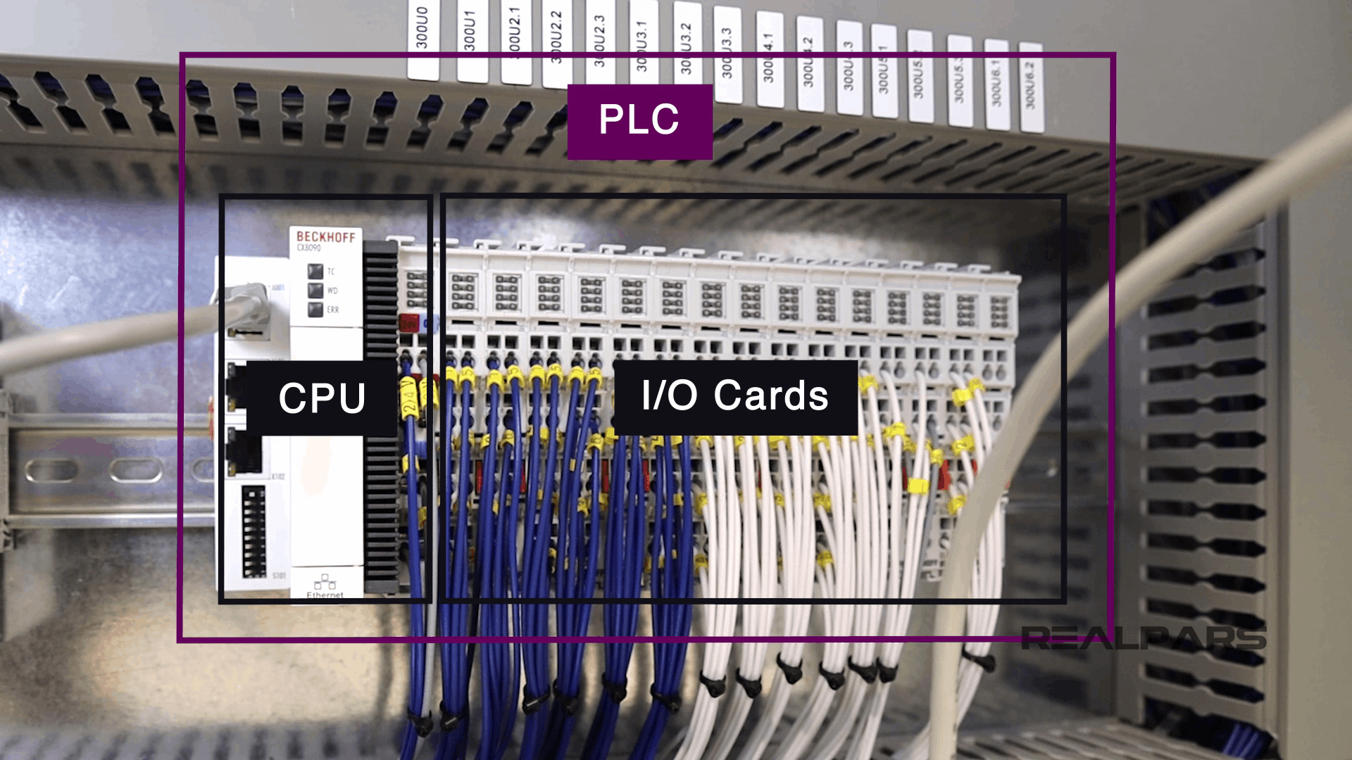
CPU
As I mentioned before, this is a BECKHOFF PLC.
The first module that we have for this PLC is a CPU.
The CPU works as the brain of the PLC.
This CPU has a few LED indicators, a couple of Ethernet ports and also a bunch of DIP switches.
Input and output cards
Next, we have the input and output cards.
Of these cards, those with blue wires are digital input, and output cards and those with the white wires are analog input and output cards.
So you see that we use separate cards for digital and analog signals.
This PLC that we have here is a unit that includes a CPU and a few input and output cards, which together make up the PLC hardware.
PLC wiring
Now let’s take a look at the wires that are connected to the PLC.
These wires come all the way through the trunking, and then they are connected to the terminals inside the pannel.
So one end of the wires is connected to the PLC cards, and the other end is connected to the terminals.
Now later, when we install this control panel on the field or the factory, the sensors will be connected to the other end of the terminals. How?
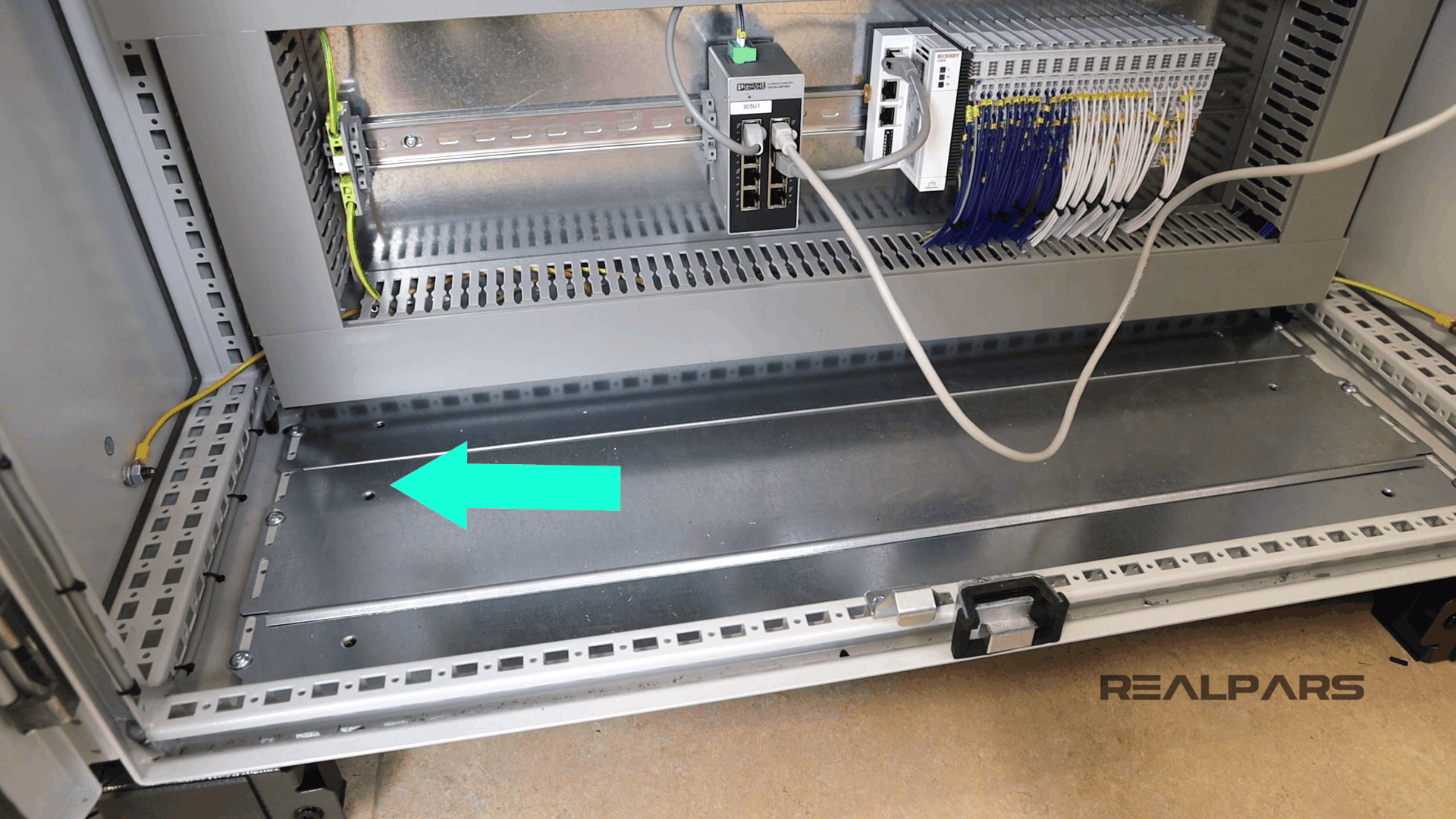
Gland plate
It’s very simple! First, we make some holes on the bottom of this panel, like the holes that we have in the image below.
This is called a gland plate and allows the cables to come into the panel.
Then, we put them into the trunking and connect them to the other end of the terminals.
Please note that we are using the term cable here instead of wire. What is the difference?
The wire is a single conductor, but a cable is a group of wires that are covered in a jacket.
So wire and cable are different. A wire is a single conductor but a cable is a group of wire. Very simple!
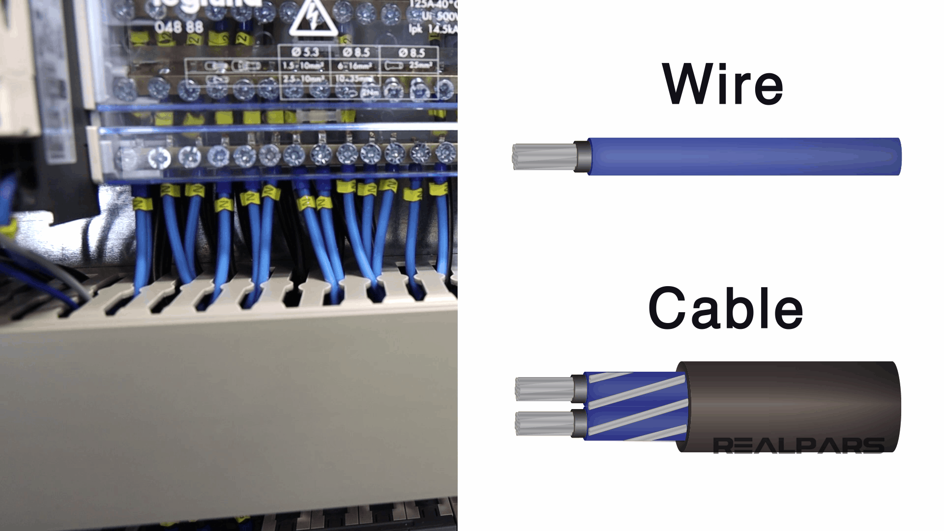
Outside of the control panel, you use cables, but inside the panel, you remove the jacket and use the wires. Why? Because inside the panel, you need to label every single wire.
Why labeling? You need to label each wire to be able to make the uniquely identifiable, which helps with troubleshooting if there is an issue.
The wire is labeled at both ends, so you know exactly where each end terminates.
Ethernet switch
Moving on, as you can see in the image below, the PLC is connected to an Ethernet switch via a cables.
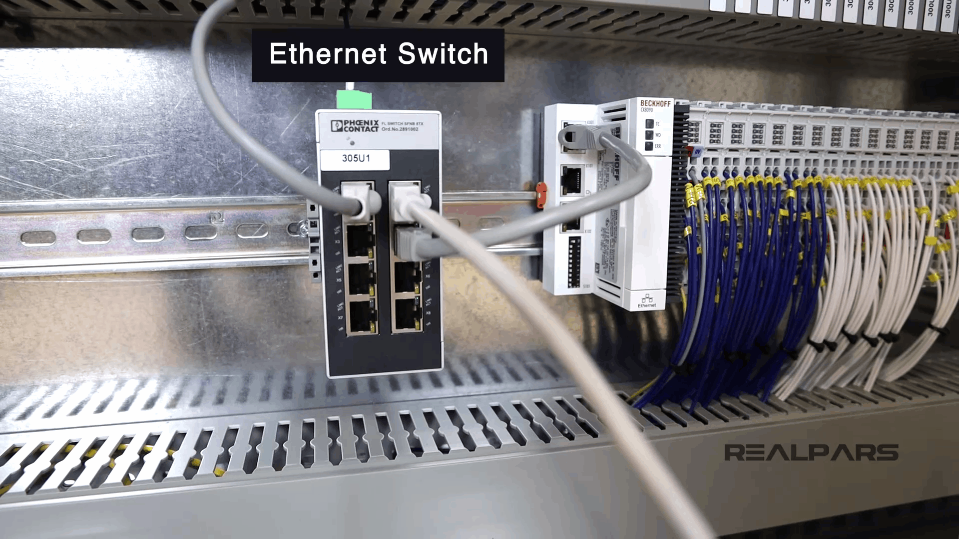
From the other end, the Ethernet switch is connected to another devices which we call Communication Interface Unit or CIU.
These interface units connect to the pumps that are installed in the field, and that’s how the PLC can control the pumps.
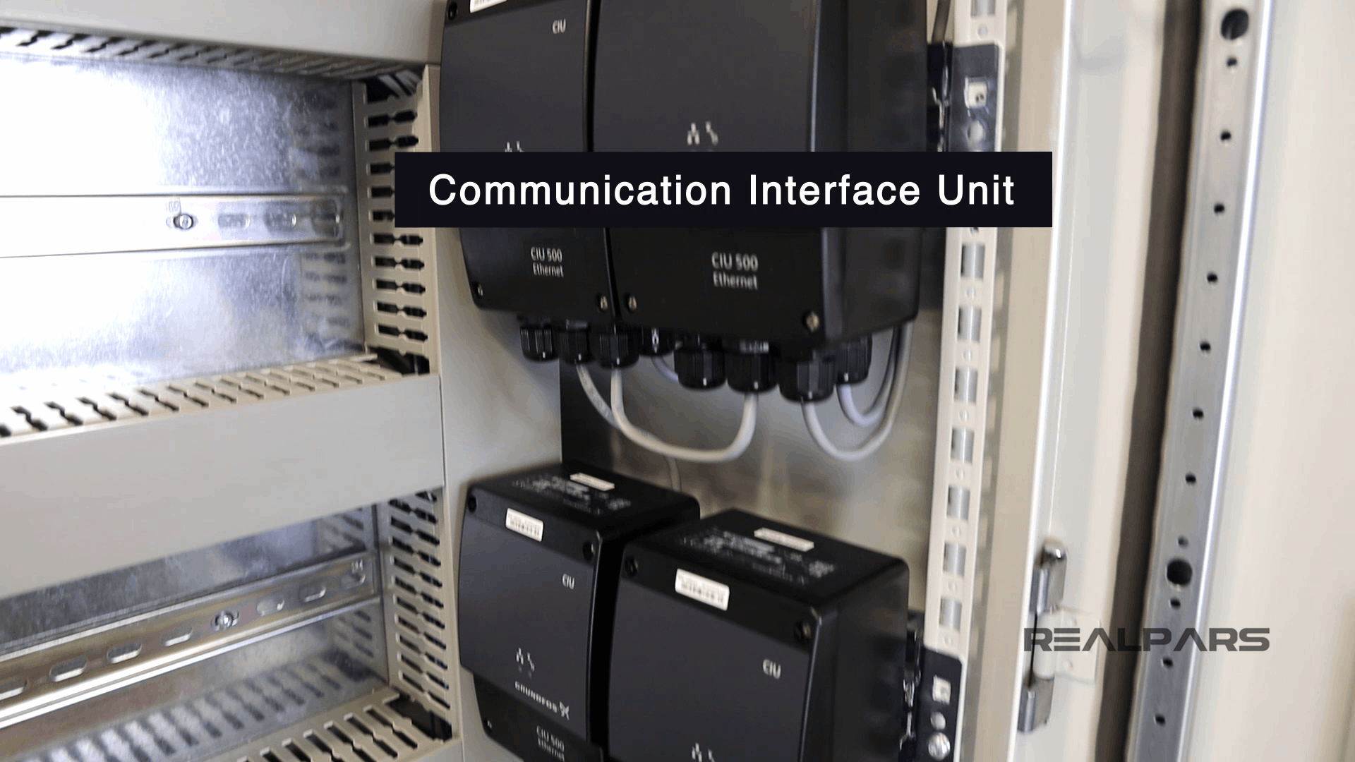
So the PLC is connected to the Ethernet switch first, then the switch is connected to the Interface Units, and then the other end of the units are connected to the pumps.
Some field devices are connected to the PLC directly via wires, and some others are connected via Ethernet cables.
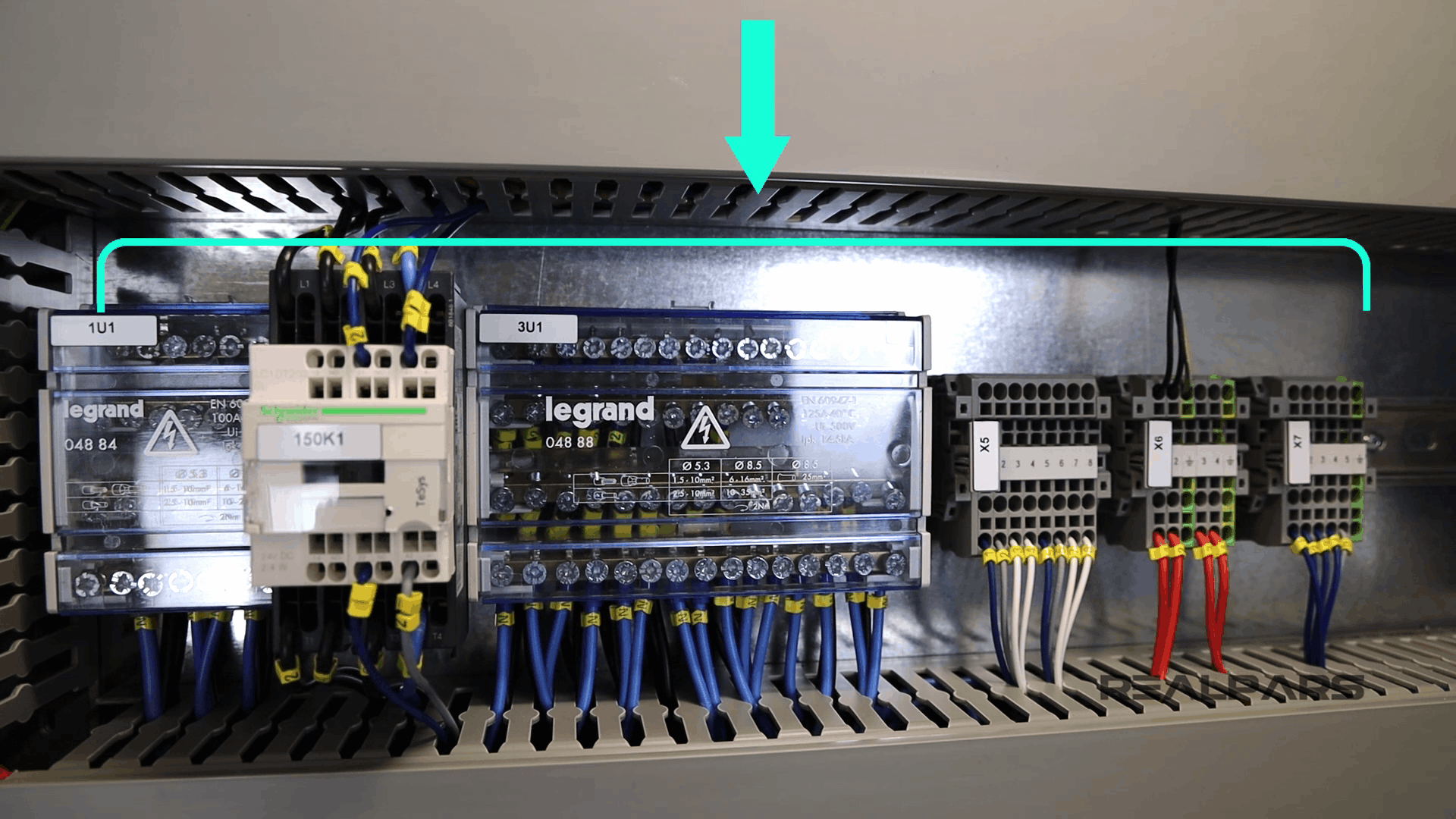
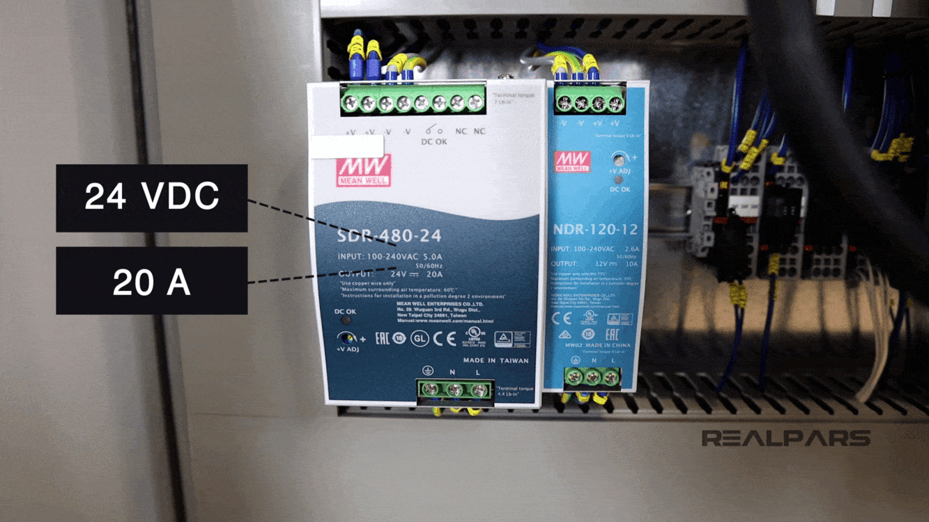
Power supplies
We also have a couple power supplies in the control panel. The bigger one in our panel has 24-Volt DC output voltage and 20A (or sometimes shortened to Amp or Amps) output current.
The small one has 12 Volt DC output voltage and 10A output current.
Both of these power supplies receive 220 Volt AC as input.
The bigger one gives you 24 Volt DC in the output, and the smaller one gives you 12 Volt DC on the output.
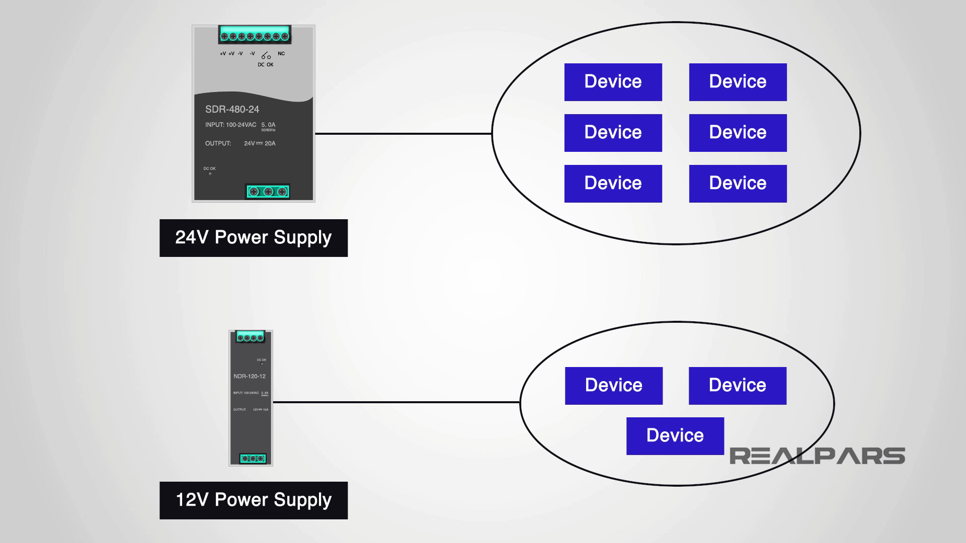
Now you may ask why we have two power supplies in this control panel with different output voltage.
Well, that is simply because we have some devices in the control panel that works with 24 Volt DC and some other devices that work with 12 Volt DC.
We use one of them to power the devices that work with 24 Volt DC and another one for powering the devices that work with 12 Volt DC.
Wonder why the 24 Volt power supply has a greater output amperage compared to the 12 Volt power supply?
This is because the number of devices, or the devices themselves, powered by the 24 Volt power supply require more input current to operate than those powered by the 12 Volt power supply.
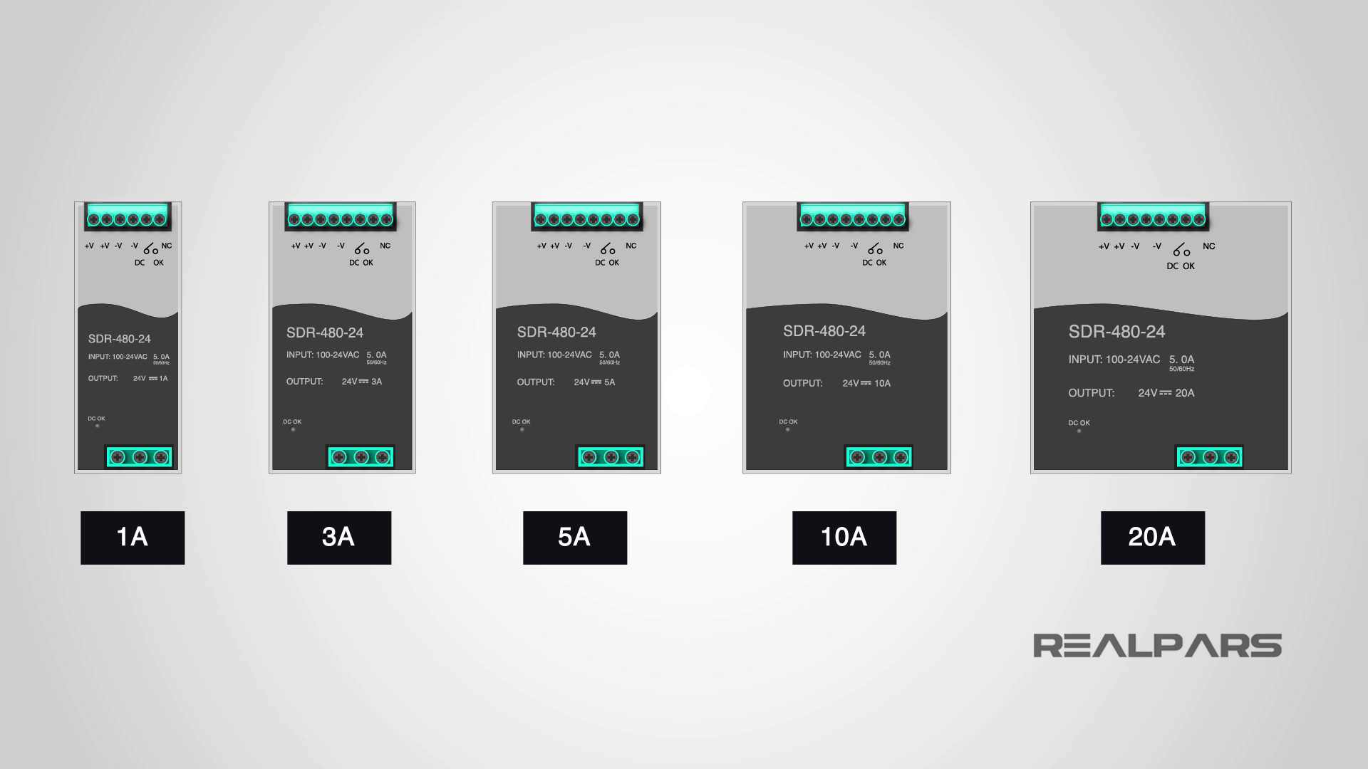
How do we size PLC power supplies?
We usually size the power supplies based on the amount of current output that we need.
For example, we have power supplies with 1 Amp, 3 Amp, 5 Amp, 10 Amp, and 20 Amp output current.
The more devices we have, the more current we need and the bigger the power supply gets. Easy, right?
Summary
So to sum it all up, here is what you learned from this article:
– We name control panels based on the number of doors that they have. For example, one-door, two-door or three-door control panel enclosures depending on how big of a panel you have. The more equipment and devices you have, the larger the control cabinet you will need.
– We usually have some switches that are connected to the PLC inputs and outputs. For example, one of these switches could be Mute Buzzer. This is the button that you use and press when there is an active alarm on the system
– You use the big red Emergency Shutdown push button or the E-Stop as it’s often called to shut down the whole system when there is an emergency.
– A PLC is a unit that usually includes a CPU and a few input and output cards.
– What is the difference between a wire and a cable? A wire is a single conductor but a cable is a group of wires that are covered in a jacket.
– You need to label each wire to be able to make the uniquely identifiable, which helps with troubleshooting if there is an issue.
– Sometimes we have two power supplies in this control panel with different output voltage. That is simply because we have some devices in the control panel that works with 24 volt DC and some other devices that work with 12 Volt DC.
– The reason that in this control panel the 24 Volt power supply is bigger in size is simply that here we have more devices that need 24 VDC to be turned on.
– We usually size the power supplies based on the amount of current output that we need. For example, we have power supplies with 1 Amp, 3 Amp, 5 Amp, 10 Amp, and 20 Amp output current. The more devices we have, the more current we need and the bigger the power supply gets.
So this was an in-depth overview of the essential industrial electrical panel components that you see in a panel.
This article was brought to you by RealPars in partnership with Pro-control in the Netherlands.
They are experts at control system design and industrial automation. They have a team of world-class automation engineers and have been designing and implementing industrial control systems in different industries for many years.
If you want to get in contact with them, you can check out their website at pro-control.nl.
Got a friend, client, or colleague who could use some of this information? Please share this article.
The RealPars Team